
Injector for auto-injection of medication and associated method of use

Inactive Publication Date: 2011-12-29
TCB MEDICAL DEVICES
View PDF3 Cites 82 Cited by
  • Summary
  • Abstract
  • Description
  • Claims
  • Application Information

AI Technical Summary

Benefits of technology

[0010]The protective sleeve is moveably located with respect to the activation mechanism. In the first position, the sleeve is located within the activation mechanism towards its distal, back end while the device is in its non-deployed configuration. This position allows for exposure of the needle when the device is in the deployed configuration, facilitating exposure of the needle. The sleeve preferably moves from a first position to a second position. From the first position, the sleeve may preferably extend proximally from the forward facing surface of the device body into its second position to encase the needle as it is removed from the injection site after deployment. More preferably, the protective sleeve may be biased so that after injection of the liquid and removal of the needle from the patient's skin, the sleeve may automatically move to its second position to protect the user from accidental needle stick. In its first position, the protective sleeve may preferably interact with or engage the activation member so that it is prevented from moving to its second position until the activation member has moved to its second position. In its second position, the protective sleeve preferably interacts with or engages the activation member in a second way so that the sleeve may be locked or secured in the second position.
[0012]The safety mechanism is also moveably located with respect to the device body. The safety mechanism may move from a first position to a second position. In the first position, the safety mechanism prevents the crown from deforming, which secondarily prevents movement of the activation mechanism.
[0017]The depressible buttons of the safety mechanism contain distal ends that are preferably in contact with the peripheral portion of the crown of the power assembly. In the first, safety position, the depressible buttons prevent the crown from deforming by obstructing its peripheral edges. The peripheral edges of the crown, when immobilized by the safety buttons, prevent the activation mechanism from moving from its first position to its second position.
[0018]The activation mechanism preferably includes a distal portion that resides in the internal cavity of the body. The distal portion of the activation mechanism interacts with the crown of the power assembly. In its first position, the activation mechanism may preferably be in close proximity to the crown or rest against the crown. In its second position the activation mechanism causes the crown to deform, releasing the plunger arm. The activation mechanism is prevented from moving to its second position when the safety mechanism is in its first, safety position, because the safety mechanism prevents the crown from deforming. After the plunger arm has been released and the syringe has moved to its second position, the activation mechanism may move back to its first, proximal position to facilitate the encasement of the needle along with the sleeve.

Problems solved by technology

Conditions requiring such treatment may result from a variety of causes.
Among the most serious of those conditions is anaphylaxis (a severe allergic reaction) that, in many cases, can become fatal within minutes if left untreated.
For example, food products having even small quantities of peanuts, seafood or milk products can, in some individuals, induce severe, potentially lethal reactions.
When anaphylaxis occurs, often there is insufficient time for the patient to reach a hospital or other trained and equipped medical personnel.
Notwithstanding the severe risk involved, there is evidence that a large proportion of the population that should be carrying such an apparatus, in fact, does not.
Moreover, even for those individuals that carry such an apparatus, it has been reported that a large proportion are insufficiently familiar with its use and operation.
The injector is relatively bulky and requires training to be administered correctly since proper use of the device is not intuitive.
As a patient may only use the injector infrequently, there may be some confusion in performing the required manipulative steps, particularly when the individual experiencing anaphylaxis may be in a state of panic.
Furthermore, should it be necessary for someone other than the patient (e.g., a bystander) to administer the medication, that person may not know how to operate the injector.
Additionally, some injectors possess complicated parts requiring multiple hands for proper use and administration.
Consequently, precious time may be lost, increasing the risk to the patient.
Moreover, confusion has been reported regarding which end of the device the needle protrudes from and, as such, accidental injections into the thumb or finger of the person delivering the medicine are common.
Additionally, after the injector has been used to effect an injection, its hypodermic needle often remains exposed, presenting post-injection hazards.

Method used


Image

  • Injector for auto-injection of medication and associated method of use
  • Injector for auto-injection of medication and associated method of use
  • Injector for auto-injection of medication and associated method of use

Examples


Embodiment Construction

[0039]Certain illustrative embodiments of the invention will now be described with reference to the drawings. In general, such embodiments relate to embodiments of an apparatus for injecting a dose of medication, more specifically, a disposable, portable injector for administering a single dose of Epinephrine in an emergency situation. It should be understood however that the invention may have other applications and uses and should not be limited to the structure or use described and illustrated. For example, the injector apparatus may be used to administer other liquids or medication aside from Epinephrine. In addition, the injector apparatus may be designed to be reusable, etc.

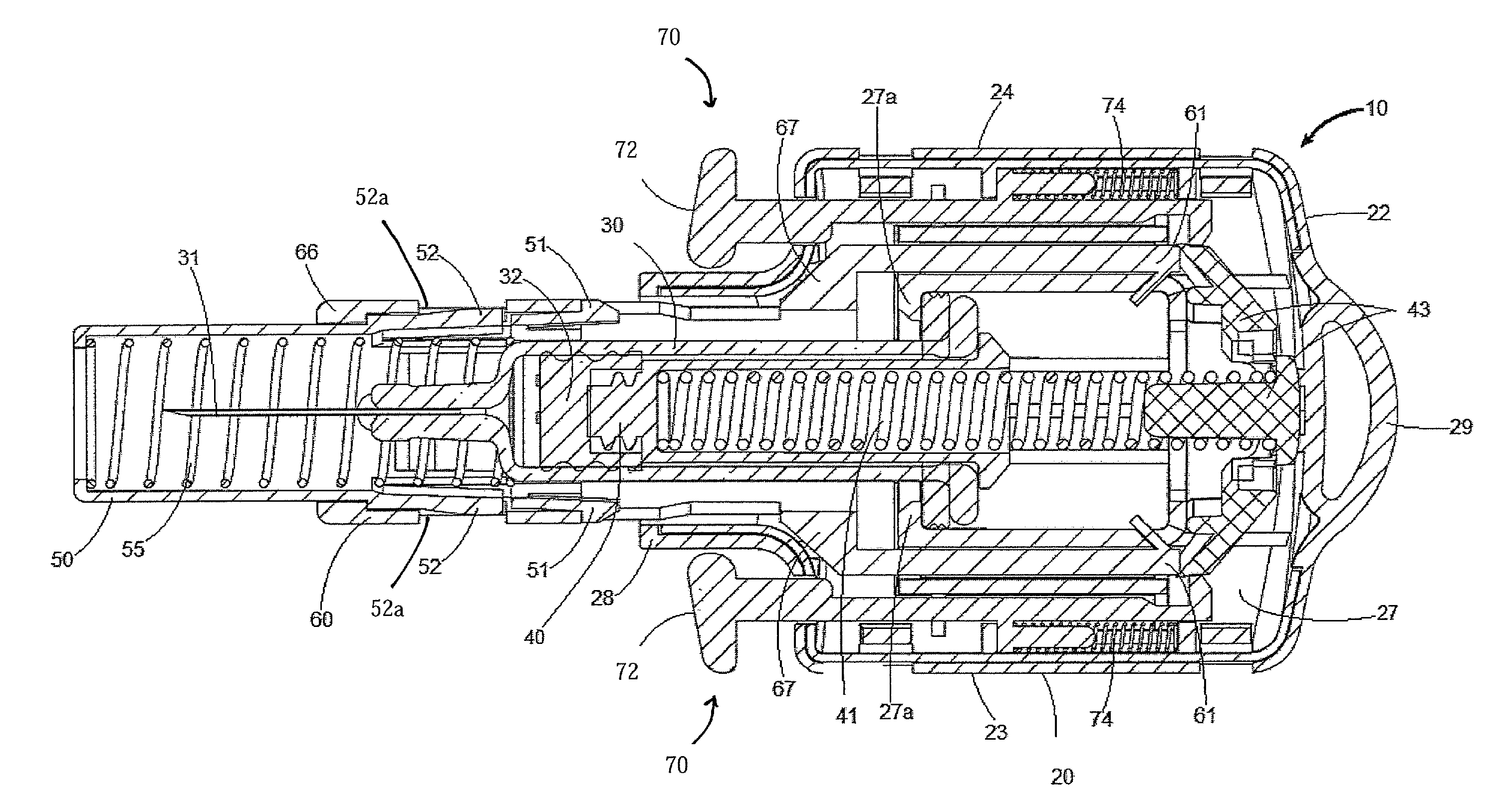
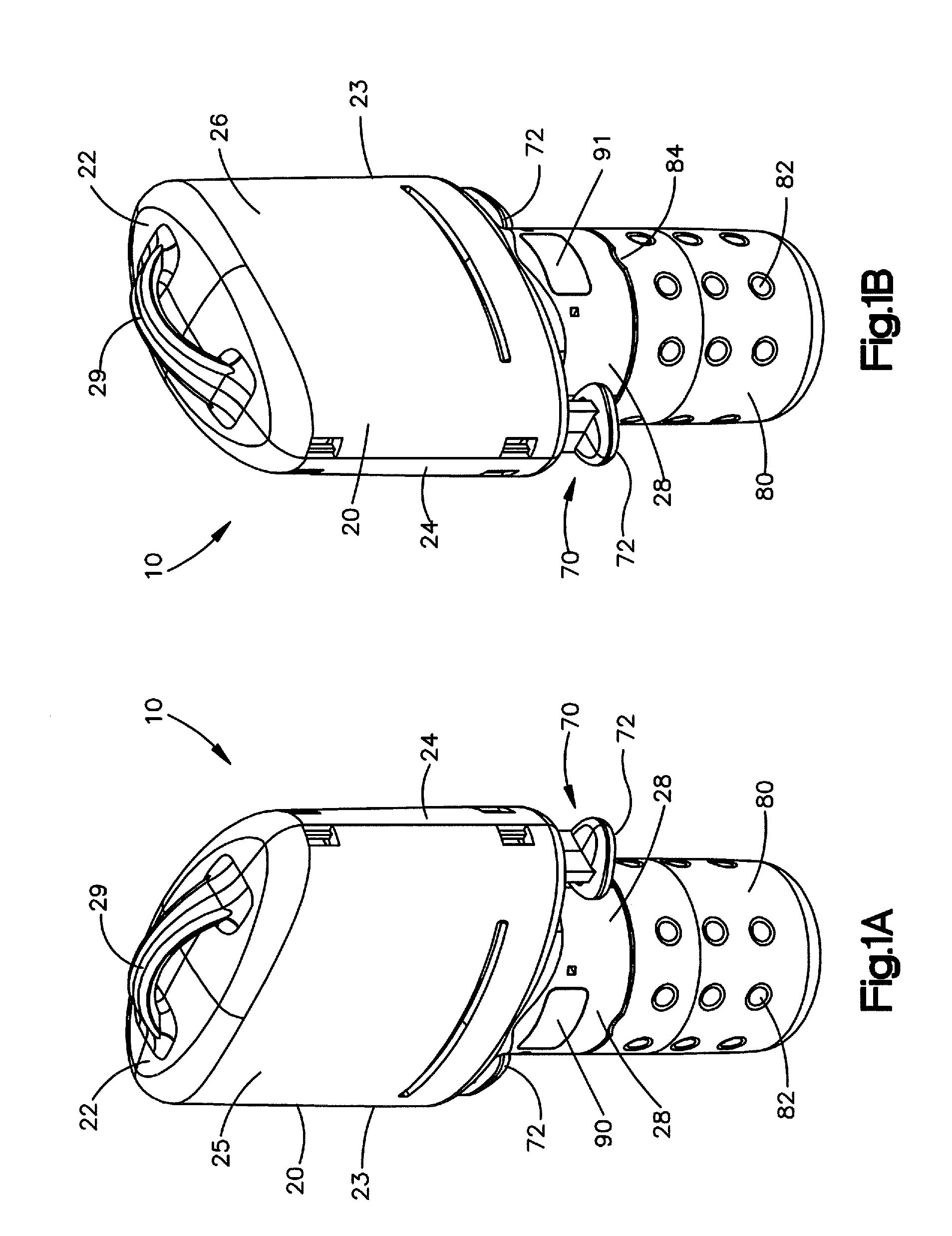
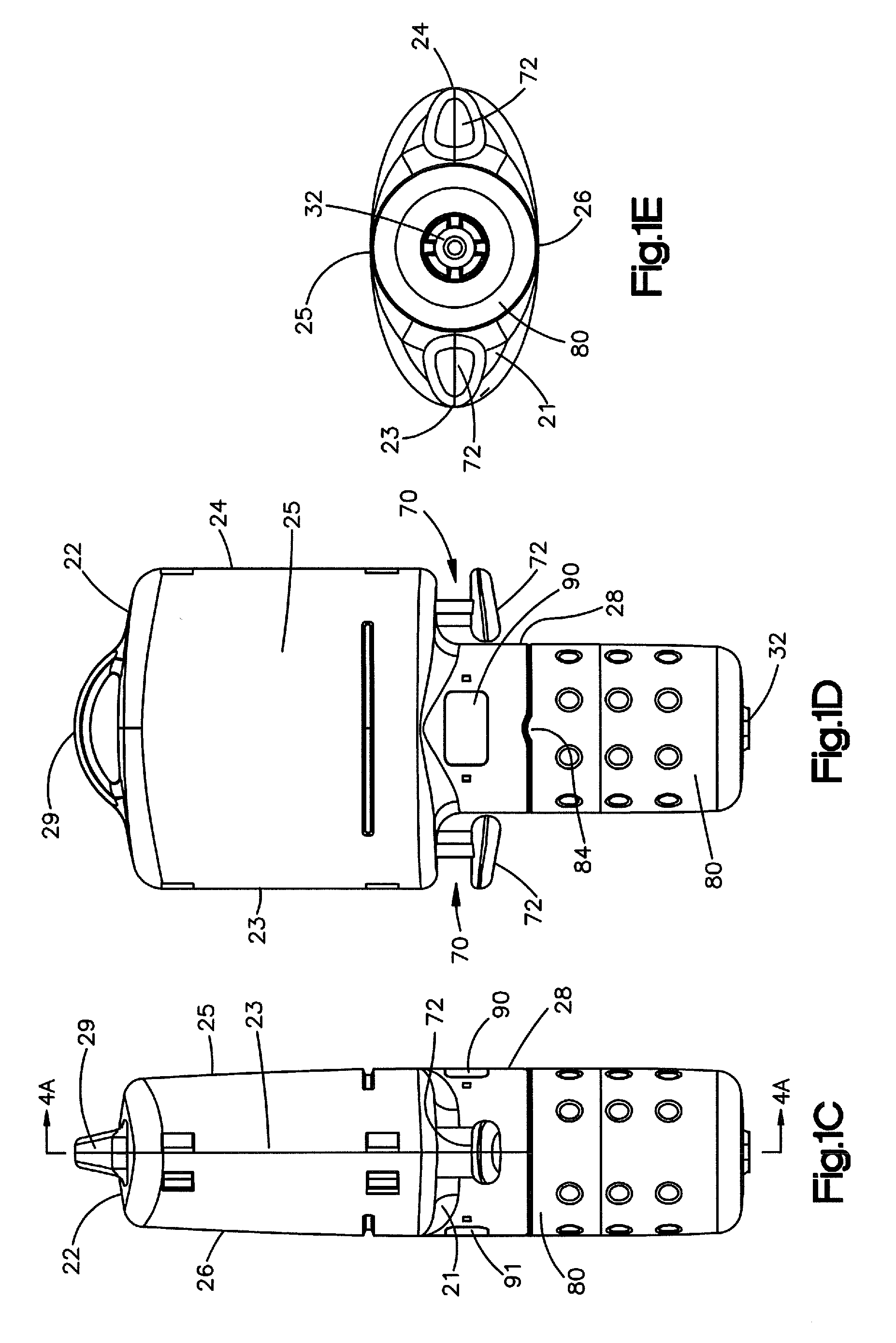
[0040]Turning first to the embodiment of FIGS. 1A-E as will be described in greater detail below, the injector 10 preferably includes a body 20, a syringe or cartridge (hereinafter “syringe”) 30 with attached needle 31, a power assembly 40, a protective sleeve 50, an activation member 60, and a safety mecha...


PUM


Abstract

A key-shaped portable injector for delivering a dose of medication, the injector preferably including a cap, a body having an internal cavity, a syringe or cartridge with an attached needle within the internal cavity, a protective sleeve, an activation mechanism and a safety mechanism wherein the injector is reconfigurable from a first, non-deployed configuration where the activation mechanism, syringe or cartridge and a safety mechanism are all in a first position with respect to the body to a second, deployed configuration where the safety mechanism, activation mechanism, and syringe or cartridge are all in a second position with respect to the body and to a third, depleted configuration where the activation mechanism is back to its first position and a protective sleeve is in its second position.

Description

CROSS REFERENCE TO RELATED APPLICATIONS[0001]The present application claims priority to and the benefit of the filing date of U.S. Provisional No. 61 / 357,618, filed Jun. 23, 2010, which application is incorporated herein fully by this reference.FIELD OF INVENTION[0002]The present invention relates generally to an injector apparatus and method for the automatic injection of a liquid and, more specifically, to an injector requiring only one hand for use.BACKGROUND OF THE INVENTION[0003]Certain medical conditions require immediate injection of medication. Conditions requiring such treatment may result from a variety of causes. Among the most serious of those conditions is anaphylaxis (a severe allergic reaction) that, in many cases, can become fatal within minutes if left untreated. Numerous allergens may cause anaphylaxis including insect bites, medications, latex, foods and other various chemical substances. For example, food products having even small quantities of peanuts, seafood ...

Claims


Application Information

Patent Timeline
IPC IPC(8): A61M5/32
CPCA61M5/2033A61M5/3204A61M2005/206A61M2005/3268A61M2205/586A61M5/326A61M2005/2073
Inventor BELLER, THOMAS C.FORMAN, MARK EMORTON, MATTHEW J.BEDSAUL, AMANDA D.
Owner TCB MEDICAL DEVICES
Learn More