Saw blade tooth form for abusive cutting applications

a technology for abusive cutting and saw blades, applied in the field of saw blades, can solve the problems of premature fracture or rounding, insufficiently addressing the problem of premature tooth breakage and wear, and the thicker recip blades have not satisfactorily addressed the problem, etc., to achieve the effect of practical applicability, increase the wear life of the blade, and resist wear

Active Publication Date: 2012-01-05
BLACK & DECKER INC
View PDF10 Cites 29 Cited by
  • Summary
  • Abstract
  • Description
  • Claims
  • Application Information

AI Technical Summary

Benefits of technology

[0021]One advantage of the recip blades of the present invention is that they have practical applicability in relatively abusive cutting applications, such as in demolition when cutting nail embedded wood. For example, features of the present invention are suitable for use in connection with recip blades that are relatively thick and define a relatively coarse tooth pitch, such as blades that define a thickness that is greater than about 0.05 inch (e.g., about 0.062 inch) and a tooth pitch of 10 teeth-per-inch (TPI) or coarser (e.g., 9, 8, 7, 6 and 5 TPI, and other similarly coarse pitches, such as ⅝, 6/10, 6/8 etc.). A further advantage of the recip blades of the in

Problems solved by technology

One drawback associated with such prior art recip blades is that the teeth defining such steep clearance angles are relatively weak, and thus prone to premature fracture or rounding, particularly when subjected to abusive cutting applications, such as in demolition applications where cuts are made through multiple work pieces and/or multiple materials or layers of materials, such as cutting pipes or interrupted cuts of hard objects that are embedded within softer materials, like nail embedded wood, nail or screw embedded sheetrock, or plaster bonded to metal or wood lath.
However, although beneficial, thicker recip blades have not satisfactorily addressed the problem of premature tooth breakage and wear in abusive cutting applications.
Although helpful, this feature has not satisfactorily addressed the problem.
According to conventional wisdom, if the high teeth include relatively steep primary clearance angles, or at least relatively shallow angles that are steeper than

Method used


Image

  • Saw blade tooth form for abusive cutting applications
  • Saw blade tooth form for abusive cutting applications
  • Saw blade tooth form for abusive cutting applications

Examples


Embodiment Construction

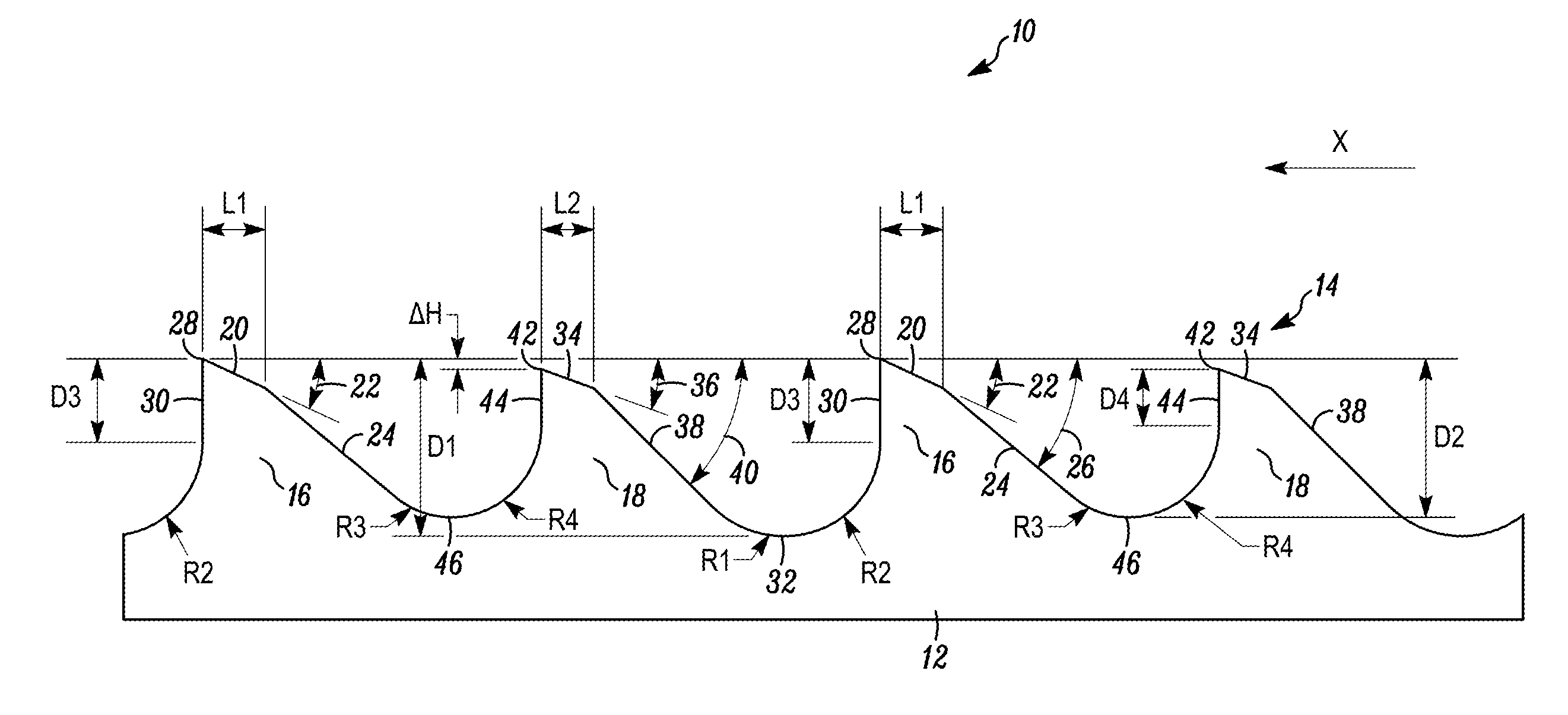
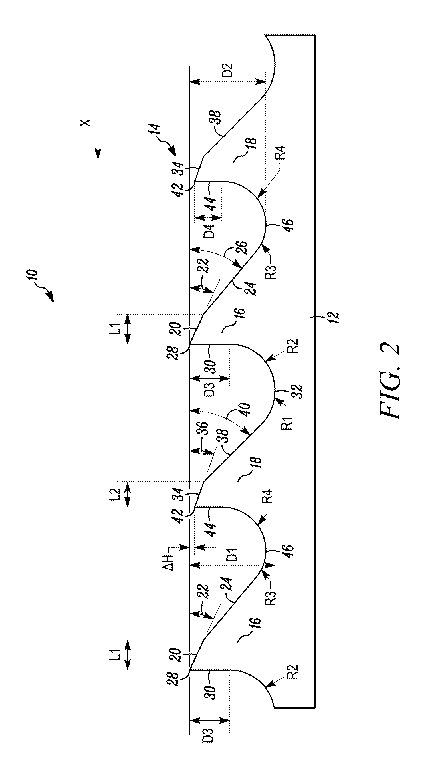
[0027]In FIG. 2, a saw blade is indicated generally by the reference numeral 10. The saw blade 10 comprises a blade body 12 and a cutting edge 14 extending along the blade body 12 and defined by a repeating pattern of two consecutive teeth. The first tooth 16 of the repeating pattern of two consecutive teeth, in reference to the cutting direction “x” of the blade 10, defines a height that is greater than the height of the subsequent second tooth 18. The first or high tooth 16 defines a primary clearance surface 20 defining a relatively shallow primary clearance angle 22, a secondary clearance surface 24 defining a relatively steep secondary clearance angle 26 compared to the primary clearance surface, a tip 28, a rake face 30 located on the opposite side of the tip 28 relative to the primary clearance surface 20, a gullet 32 defining a depth D1, a first gullet radius R1 located on an opposite side of the gullet 32 relative to the rake face 30, and a second gullet radius R2 located b...


PUM

PropertyMeasurementUnit
Timeaaaaaaaaaa
Thicknessaaaaaaaaaa
Thicknessaaaaaaaaaa

Abstract

A recip saw blade has a blade body and a cutting edge extending along the blade body and defined by a repeating pattern of two consecutive teeth suitable for abusive cutting applications. The blade defines a relatively coarse tooth pitch. The two consecutive teeth, which may be bi-metal, include a high tooth and a relatively low tooth in comparison to the high tooth. Each high tooth and low tooth include a primary clearance surface defining a relatively shallow primary clearance angle that is about 28° or less, and a secondary clearance surface defining a relatively steep secondary clearance angle in comparison to the primary clearance angle. The primary clearance angle of the high tooth is steeper than the primary clearance angle of the low tooth, such as between about 23° and 28°, and the secondary clearance angle of the high tooth is shallower than the secondary clearance angle of the low tooth.

Description

FIELD OF THE INVENTION[0001]The present invention relates to saw blades, and more particularly, to saw blades, such as reciprocating saw or recip blades, with tooth forms suited for abusive cutting applications.BACKGROUND INFORMATION[0002]A reciprocating saw machine is a power saw that includes a chuck for releasably engaging the saw blade and driving the saw blade in a reciprocating motion through a work piece. The reciprocating motion can be an orbital cutting action, a straight or linear cutting action, or an angled cutting action. The length or stroke of the reciprocating motion is typically about 1½ inches or less. Reciprocating saws are sometimes referred to as recip saws, jig saws, and power hack saws, and the term reciprocating saw is used herein without limitation to mean reciprocating saw machines, jigsaw machines, and portable power hack machines. Reciprocating saws are typically driven by electric motors (e.g., cord or cordless saws) or are pneumatically driven. Well-kno...

Claims


Application Information

Patent Timeline
IPC IPC(8): B27B33/02B23D61/12
CPCB23B51/0406B23D61/121B23B2251/14B23B2251/28Y10T83/935Y10T83/9454Y10T83/9358B27B33/02B23B51/04
Inventor ELLISTON, ASIFKORB, WILLIAM B.HAMPTON, STEPHEN A.
Owner BLACK & DECKER INC
Why Eureka
Try Eureka