Acu-spray aerosol straw systems

a technology of aerosol cans and cans, which is applied in the direction of liquid transfer devices, instruments, liquid handling, etc., can solve the problems of disproportionately fast use of gas propellant to the fluid itself, preventing consumers from accessing the remaining contents of aerosol cans, and unable to direct the can at the proper angle to efficiently and effectively dispense the produ

Inactive Publication Date: 2012-01-05
BARBIERI RICHARD G
View PDF11 Cites 12 Cited by
  • Summary
  • Abstract
  • Description
  • Claims
  • Application Information

AI Technical Summary

Benefits of technology

[0015]The present invention, the Acu-Spray Aerosol Straw System holds significant improvements to existing aerosol dispensing methods. For purposes of summarizing the invention, certain aspects, advantages, and novel features of the invention have been described herein. It is to be understood that not necessarily all such advantages may be achieved in accordance with any one particular embodiment of the invention. Thus, the invention may be embodied or carried out in a manner that ...

Problems solved by technology

However, when a can is tilted, the gas propellant may be used up at a disproportionately fast rate to the fluid itself.
This prevents consumers from being able to access the remaining contents of the aerosol cans.
A...

Method used


Image

  • Acu-spray aerosol straw systems
  • Acu-spray aerosol straw systems
  • Acu-spray aerosol straw systems

Examples


Embodiment Construction

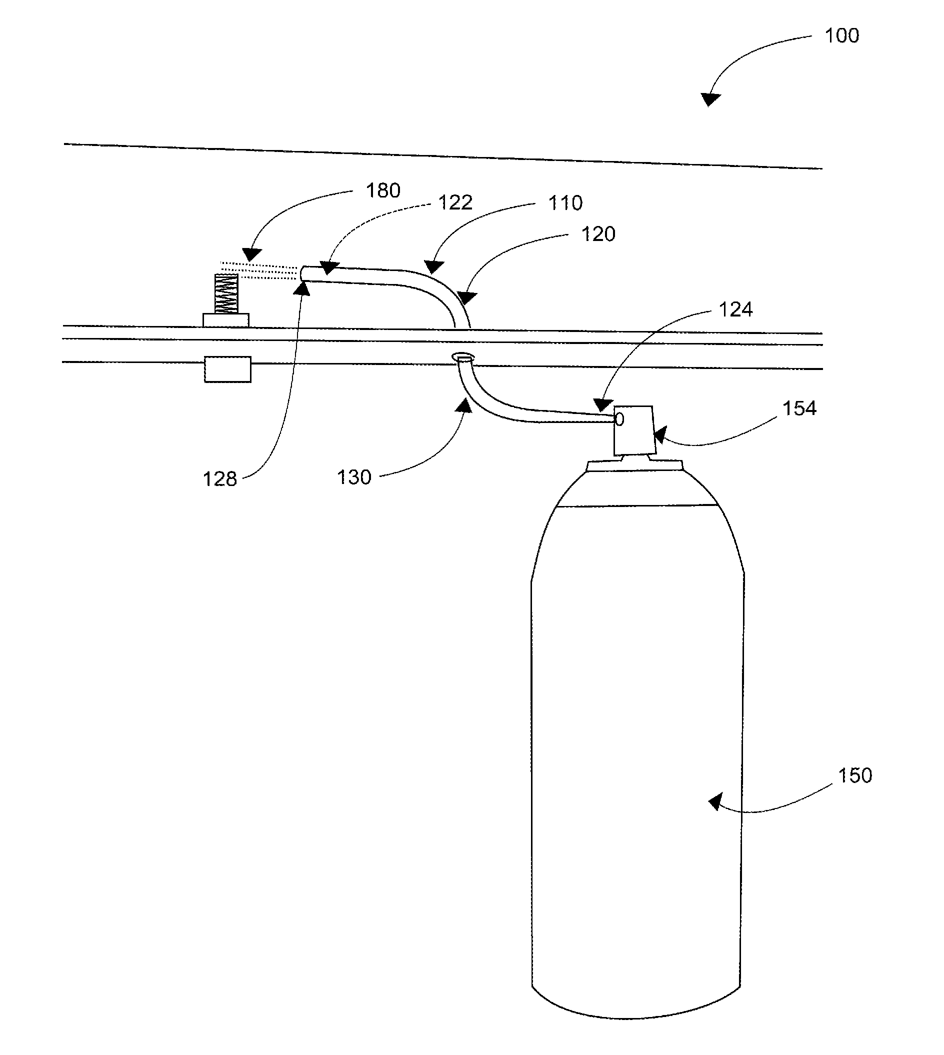
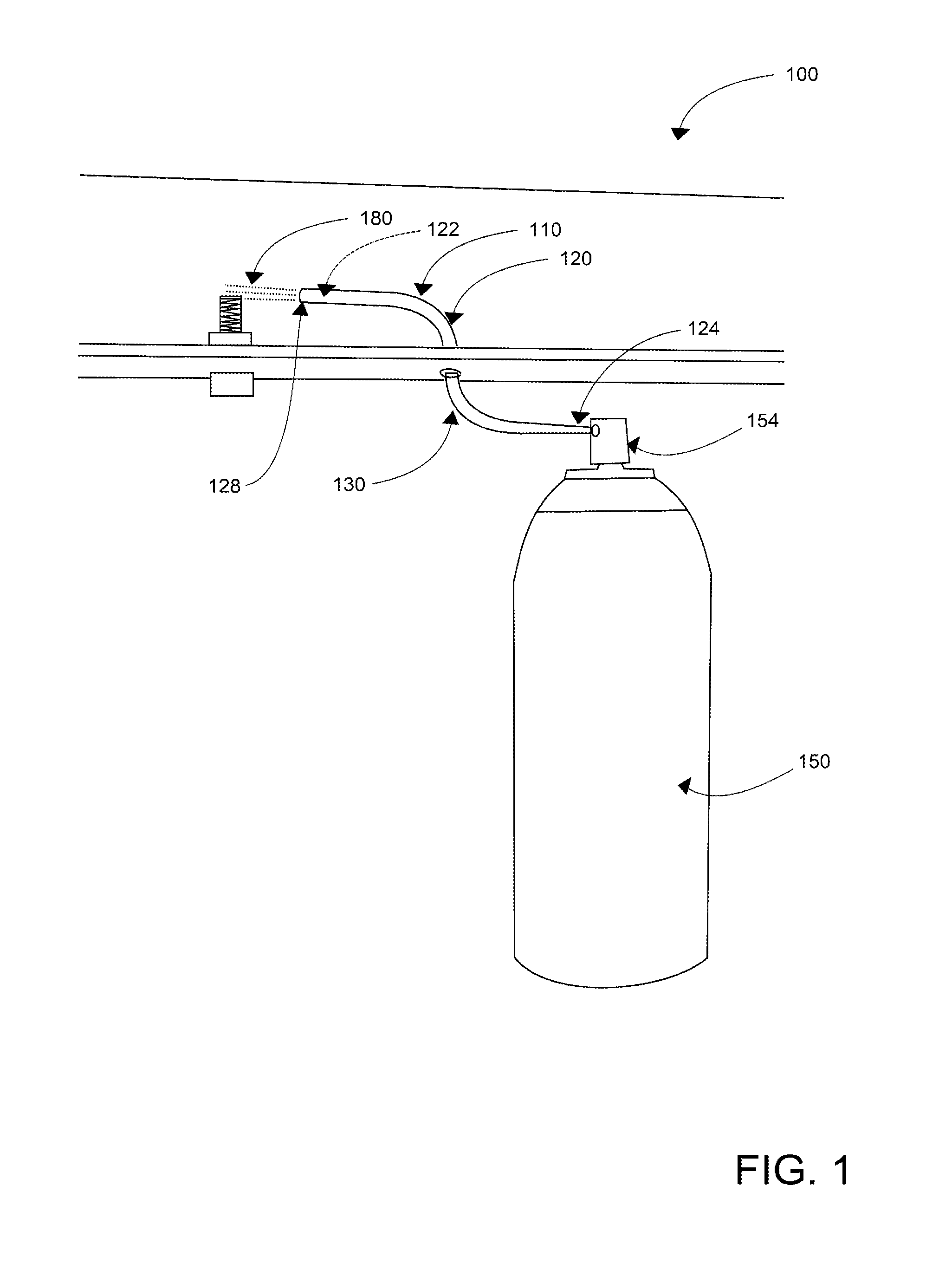
[0023]As discussed above, embodiments of the present invention relate to a dispensing means and device and more particularly to acu-spray aerosol straw system 100 as used to improve the efficiency, effectiveness by which propelled fluid(s) may be dispensed into user-preferred locations.

[0024]Generally speaking, acu-spray aerosol straw system 100 of the present invention permits pressurized container 150 to be held upright while dispensing an even stream of a user designated product from several different angles; the preferred positioning being a substantially vertically-oriented position when spray-delivering propelled fluid(s).

[0025]Referring now more specifically to the drawings by numerals of reference there is shown in FIG. 1-4, perspective views illustrating acu-spray aerosol straw system 100 in various ‘in-use’ conditions, according to embodiments of the present invention. Aerosol straw system 100 preferably comprises bendable fluid communicator 110. Bendable fluid communicato...


PUM


Abstract

Acu-Spray Aerosol Straw is designed to allow the contents of a pressurized container to be dispensed at virtually any angle. Acu-Spray Aerosol Straw comprises a bendable, plastic straw. A wire is molded into the sidewall of the straw or molded integral to the straw tube as supporting means. The wire may be housed in a plastic casing and then molded onto the side of the original aerosol straw. The molding together of the wire that is encased and the straw-tube effectively prevents the separation of the two components due to bending. The bendable straw in combination with the wire is bendably-manipulatable such that a propelled fluid from a pressurized container is strategically dispensed onto a user-defined location. The device may be detachable from the nozzle to prevent breakage while the can is in storage. In certain embodiments the device may comprise a non-wire version wherein the bendable straw may be a non-bendable rigid structure. The rigid straw embodiment may comprise L-shaped, C-shaped, V-shaped configurations and/or other such shapes.

Description

CROSS-REFERENCE TO RELATED APPLICATION[0001]The present application is related to and claims priority from prior provisional application Ser. No. 61 / 359,921, filed Jun. 30, 2010 which application is incorporated herein by reference.COPYRIGHT NOTICE[0002]A portion of the disclosure of this patent document contains material which is subject to copyright protection. The copyright owner has no objection to the facsimile reproduction by anyone of the patent document or the patent disclosure, as it appears in the Patent and Trademark Office patent file or records, but otherwise reserves all copyright rights whatsoever. 37 CFR 1.71(d).BACKGROUND OF THE INVENTION[0003]The following includes information that may be useful in understanding the present invention(s). It is not an admission that any of the information provided herein is prior art, or material, to the presently described or claimed inventions, or that any publication or document that is specifically or implicitly referenced is pr...

Claims


Application Information

Patent Timeline
IPC IPC(8): B67D7/00B67D7/06
CPCB65D83/303B05B11/0089
Inventor BARBIERI, RICHARD G.
Owner BARBIERI RICHARD G
Why Eureka
Try Eureka