Magnifying Observation Apparatus

a technology of observation apparatus and magnification, which is applied in the direction of material analysis using wave/particle radiation, instruments, nuclear engineering, etc., can solve the problems of difficult visual field search, low magnifying power of electron microscope, and differences in display image sizes, so as to facilitate comparative observation, enhance the degree of freedom of observation, and improve convenience

Inactive Publication Date: 2012-01-05
KEYENCE
View PDF24 Cites 32 Cited by
  • Summary
  • Abstract
  • Description
  • Claims
  • Application Information

AI Technical Summary

Benefits of technology

[0028]According to still another embodiment of the invention, in the magnifying observation apparatus, the optical imaging device may include an optical magnifying power reading section that reads the set magnifying power. With this configuration, the magnifying observation apparatus side can recognize the optical zoom lens magnifying power manually set by the user, and the pieces of processing such as the magnifying power conversion can smoothly be performed.
[0029]According to still another embodiment of the invention, in the magnifying observation apparatus, the optical magnifying power reading section may read the magnifying power of the optical image, the magnifying power conversion section may convert the magnifying power of the electron microscope image corresponding to the read optical magnifying power, and the display section may display the electron microscope image of the converted magnifying power. With this configuration, the electron microscope image having the magnifying power corresponding to the optical image can automatically be obtained or the obtained electron microscope image is enlarged and reduced, and the image can automatically be displayed on the display section. Therefore, the user can confirm the images having the same magnifying power as the optical image and the electron microscope image to facilitate the comparative observation.
[0030]According to still another embodiment of the invention, in the magnifying observation apparatus, the converted magnifying power converted by the magnifying power conversion section may be switched between a state in which the converted magnifying power is displayed on the display section and a state in which the converted magnifying power is not displayed. With this configuration, the display and the non-display of the converted magnifying power can be switched according to the application and purpose of the observation to enhance a degree of freedom of the observation.
[0031]According to still another embodiment of the invention, a magnifying observation apparatus may include: a plurality of observation devices; a specimen chamber whose internal space can be decompressed; a first specimen stage on which a first specimen of an observation target is placed; an electron beam imaging device as a first observation device for obtaining an electron microscope image in the specimen chamber; an electron microscope magnifying power adjusting section that adjusts an electron microscope magnifying power of the electron microscope image obtained by the electron beam imaging device; a second specimen stage on which a second specimen of an observation target is placed; an optical imaging device as a second observation device for obtaining an optical image of the second specimen; an optical magnifying power adjusting section that adjusts an optical magnifying power, the optical magnifying power being a magnifying power of the optical image obtained by the optical imaging device, the optical magnifying power being determined on a basis different from that of the electron microscope magnifying power; a display section that displays the electron microscope image of the first specimen obtained by the electron beam imaging device and the optical image of the second specimen obtained by the optical imaging device while switching between the electron microscope image and the optical image, or simultaneously displays the electron microscope image and the optical image; and a magnifying power conversion section that recognizes a magnifying power of an image obtained by one of the electron beam imaging device and the optical imaging device and converts the magnifying power, which is used to obtain an image having a magnifying power substantially identical to that of the image, by the other observation device into a magnifying power on a basis of the other observation device. With this configuration, in the observation in which two specimen images are obtained at the same size to compare the two specimen images, the magnifying power display of the different observation devices can be unified, and the convenience can be improved when the user performs the magnifying power adjusting work.
[0032]According to still another embodiment of the invention, in the magnifying observation apparatus, a controller that controls the electron beam imaging device may also control the optical imaging device. With this configuration, the electron beam imaging device and the optical imaging device are advantageously connected to one controller, and the magnifying powers on an originally different basis can be unified to conveniently perform the control.

Problems solved by technology

Although the electron microscopes such as the SEM, the TEM, and the STEM are effectively used in the observation at a high magnifying power, the electron microscopes do not well display at a low magnifying power.
Therefore, it is difficult to perform visual field search that is work to finally find a site to be observed on the specimen.
However, because the electron microscope and the optical microscope are designed by different concepts with respect to magnifying powers, unfortunately the sizes of the display images differ from each other even if the magnifying powers have the same numerical value.
As a result, when an operator who is a user tries to obtain the optical image and the electron microscope image of the same size, the user needs to understand the difference of a magnifying power determining method in each observation device, and it has been difficult for the user to easily set the magnifying powers of the observation devices.

Method used


Image

  • Magnifying Observation Apparatus
  • Magnifying Observation Apparatus
  • Magnifying Observation Apparatus

Examples


second embodiment

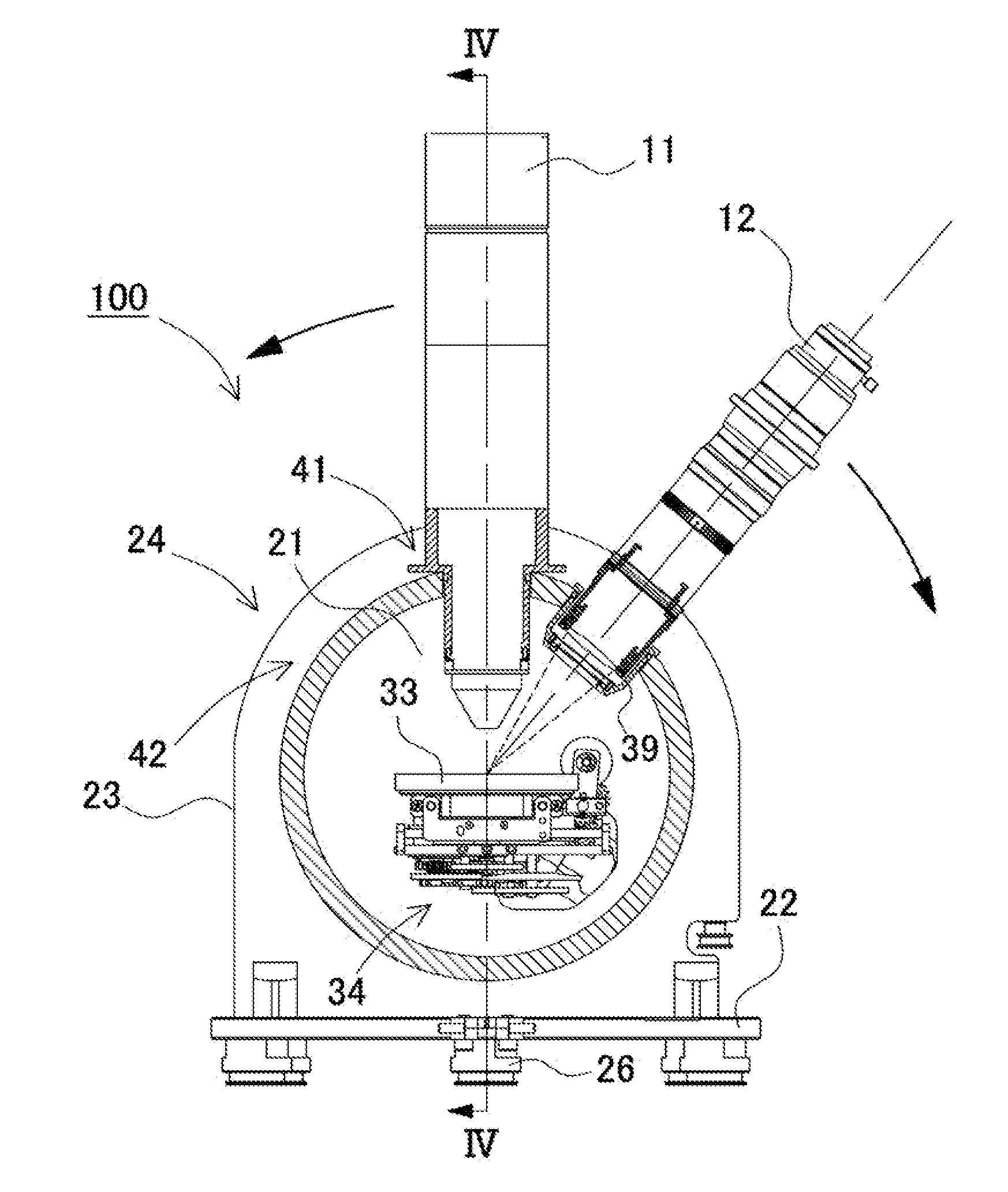
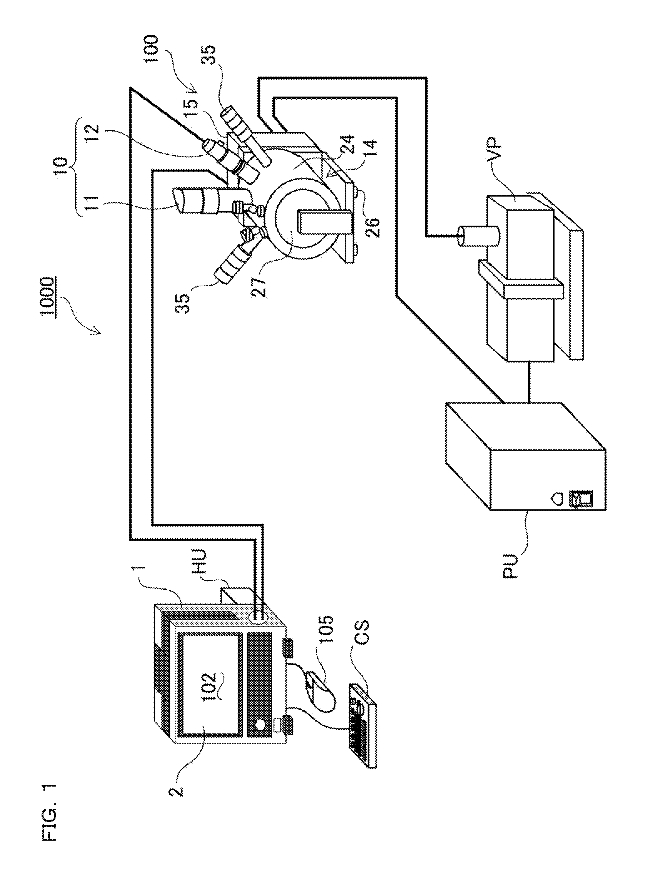
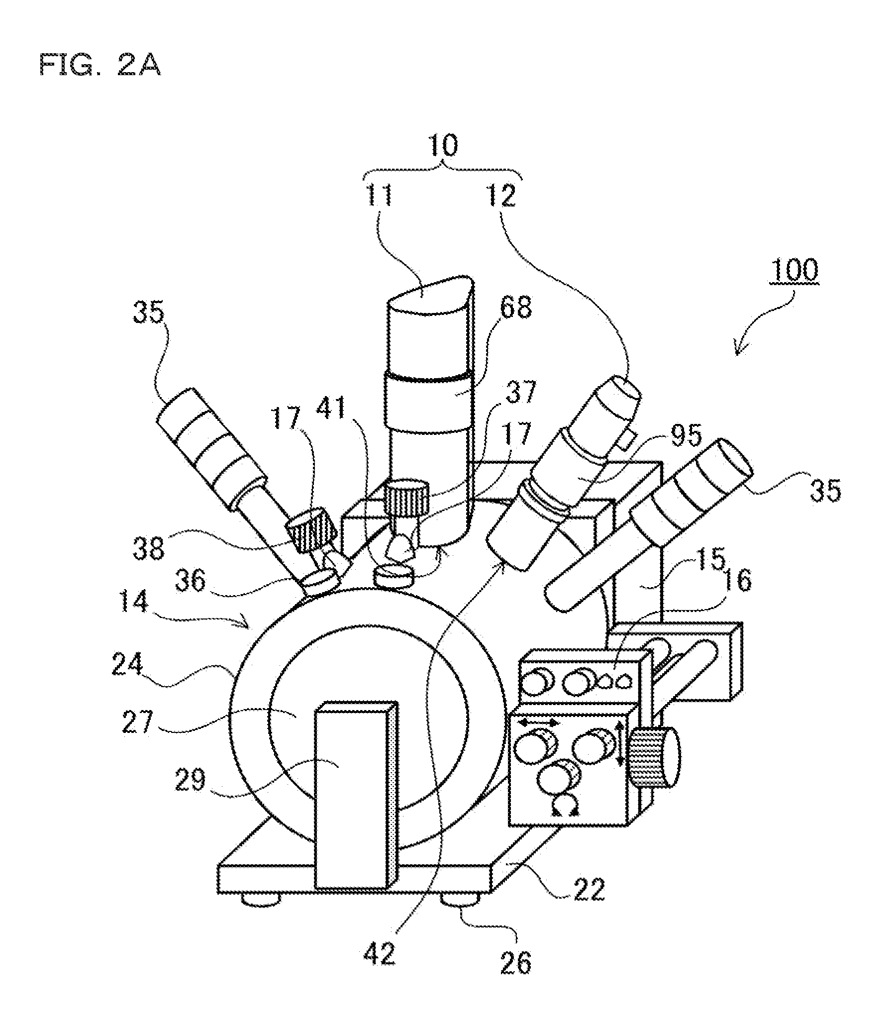
[0210]In the above example, the optical imaging device 12 and the electron beam imaging device 11 are combined by way of example. The present invention can be applied to not only the configuration in which the optical imaging device 12 and the electron beam imaging device 11 are combined but also the configuration in which the optical imaging device 12 and the electron beam imaging device 11 are added if needed. For example, as described above, the magnifying observation system illustrated in the block diagram in FIG. 18 can be configured by detachably mounting the optical imaging device 12 on the magnifying observation system with the mount 39 interposed therebetween. Thus, the optical imaging device 12 can be added if needed while the magnifying observation system is used as the electron microscope. Therefore, the useful magnifying observation system having excellent flexibility and extendibility in which options can be added and removed according to the observation application ca...


PUM

PropertyMeasurementUnit
offset angleaaaaaaaaaa
angleaaaaaaaaaa
offset angleaaaaaaaaaa

Abstract

Work to obtain an optical and an electron microscope images at an identical display size is facilitated. A magnifying observation apparatus includes: an electron beam imaging device that obtains an electron microscope image in a chamber; an optical imaging device that obtains an optical image in the chamber; a moving device that moves the both devices such that an optical axis direction of one of the both devices is aligned with an optical axis direction of the other device; a display section that displays the electron microscope and the optical images; and a magnifying power conversion section that recognizes a magnifying power of an image obtained by one of the imaging devices and converts the magnifying power, which is used to obtain an image having a display size substantially identical to that of the image, by the other device into a magnifying power on a basis of the other device.

Description

CROSS-REFERENCE TO RELATED APPLICATIONS[0001]The present application claims foreign priority based on Japanese Patent Application No. 2010-152536, filed Jul. 2, 2010, the contents of which is incorporated herein by reference.BACKGROUND OF THE INVENTION[0002]1. Field of the Invention[0003]The present invention relates to a magnifying observation apparatus in which an optical imaging device that can obtain an optical image with an optical observation device such as an optical microscope is added to an electron microscope such as a Scanning Electron Microscope (SEM).[0004]2. Description of Related Art[0005]For example, a transmission electron microscope and a scanning electron microscope are well known as a charged particle beam apparatus in which a signal obtained by irradiating an observation target specimen with a charged particle beam is detected to obtain an observation image. In the electron microscope, for example, an electron traveling direction is freely deflected and an image...

Claims


Application Information

Patent Timeline
Patent Type & Authority Applications(United States)
IPC IPC(8): G01N23/00
CPCG02B21/0004G02B21/26G02B21/365H01J37/28H01J37/16H01J37/226H01J37/228H01J37/023
Inventor TAKAGI, SHIGENORI
Owner KEYENCE
Why Eureka
Try Eureka