Voltage regulation circuit

a voltage regulation circuit and circuit technology, applied in the field of semiconductor circuits, can solve the problems of degrading operation speed and increasing circuit area, and achieve the effect of increasing current driving force and reducing circuit area

Active Publication Date: 2012-01-05
SK HYNIX INC
View PDF5 Cites 7 Cited by
  • Summary
  • Abstract
  • Description
  • Claims
  • Application Information

AI Technical Summary

Benefits of technology

[0009]A voltage regulation circuit which may reduce circu...

Problems solved by technology

If the size of the transistor is increased, the circuit area inc...

Method used


Image

  • Voltage regulation circuit
  • Voltage regulation circuit
  • Voltage regulation circuit

Examples


Embodiment Construction

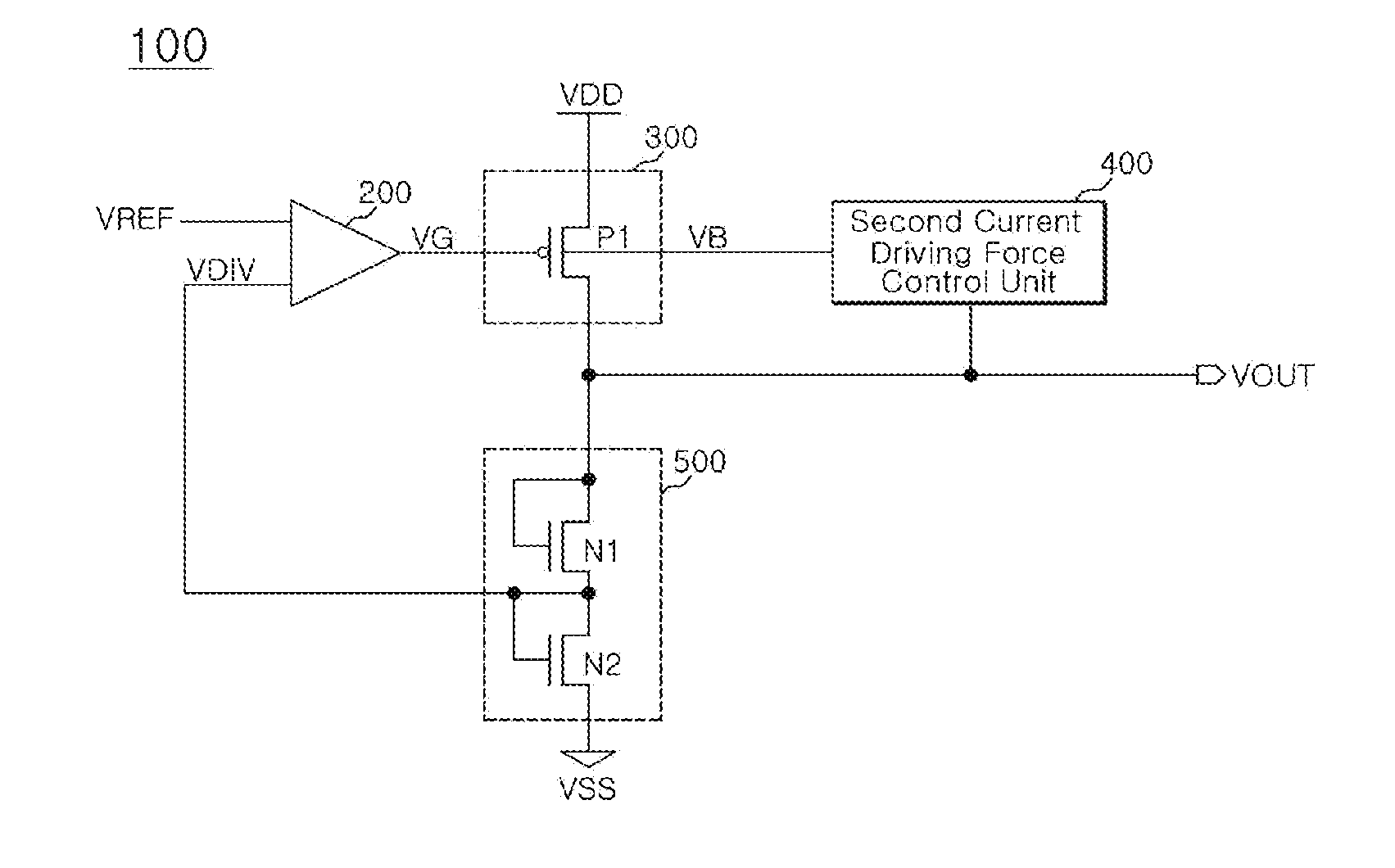
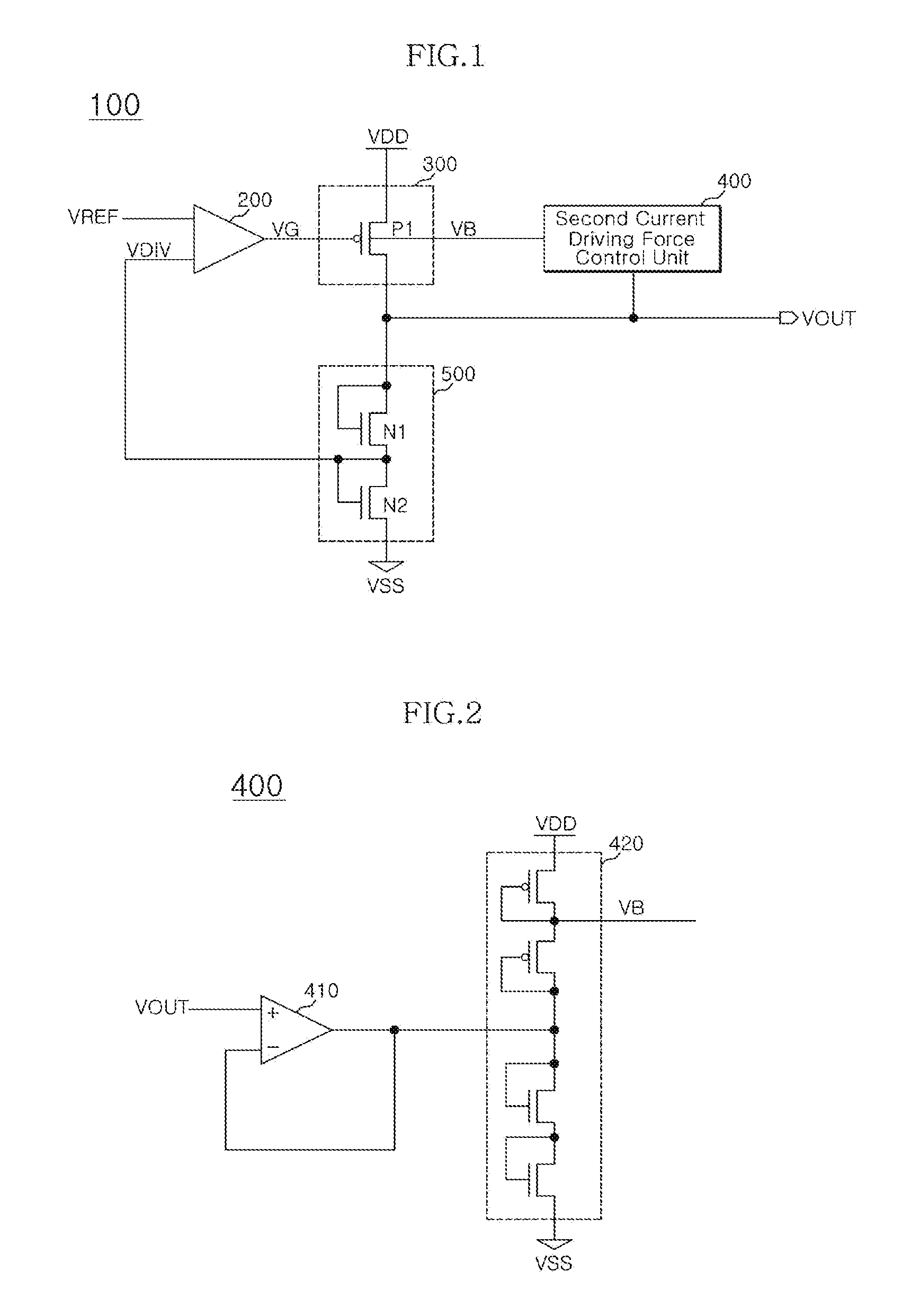
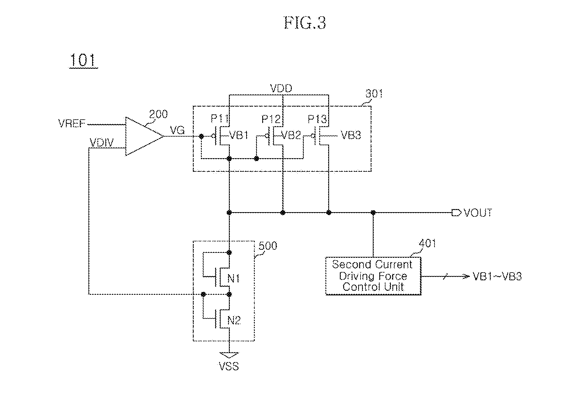
[0017]Reference will now be made in detail to the exemplary embodiments consistent with the present disclosure, examples of which are illustrated in the accompanying drawings. Wherever possible, the same reference characters will be used throughout the drawings to refer to the same or like parts.

[0018]Before describing the embodiments, the operation principle of the embodiments will be described below.

[0019]A current driving force I of a saturated region can be expressed with the following equation.

I=12μpCoxWL(Vsg-Vthp)2

[0020]A current driving force I of a linear region can be expressed with the following equation.

I=μpCoxWL{(Vsg-Vthp)Vsd-12Vsd2}

[0021]It can be readily seen from the above equations that a gate level Vsg and a threshold voltage of a transistor are largely involved in the control of a current driving force.

[0022]That is to say, it can be understood that a current driving force increases as a threshold voltage decreases.

[0023]A threshold voltage VT can be expressed with...


PUM


Abstract

A voltage regulation circuit includes: a first voltage divider that divides a regulation voltage with a predetermined division ratio to generate a division voltage; a first current driving force control unit configured to compare a reference voltage with the division voltage and generate a first control signal; a current driving unit configured to generate a driving current with a variable driving force based on the first control signal and a second control signal, and generate the regulation voltage; and a second current driving force control unit configured to generate the second control signal in accordance with a level variation of the regulation voltage.

Description

CROSS-REFERENCES TO RELATED APPLICATION[0001]The present application claims priority under 35 U.S.C. §119(a) to Korean Application No. 10-2010-0063999, filed on Jul. 2, 2010, in the Korean Intellectual Property Office, which is incorporated herein by reference in its entirety as if set forth in full.BACKGROUND[0002]1. Technical Field[0003]The present invention relates to a semiconductor circuit, and more particularly, to a voltage regulation circuit.[0004]2. Related Art[0005]In a semiconductor circuit, for example, a semiconductor is memory uses a voltage regulation circuit to generate various internal voltages such as a peripheral circuit voltage (VPERI) and a core voltage (VCORE) at stable levels.[0006]A conventional voltage regulation circuit may use a PMOS transistor to drive current by a power supply voltage, that is, an external voltage (VDD).[0007]A method of increasing the size of the PMOS transistor is employed as a method of increasing the current driving force of the PMOS...

Claims


Application Information

Patent Timeline
IPC IPC(8): G05F1/00
CPCG05F3/205G05F1/575
Inventor LEE, JUN GYU
Owner SK HYNIX INC
Why Eureka
Try Eureka