Apparatus for calibrated non-invasive measurement of electrical current

a non-invasive, electrical current technology, applied in the direction of dynamo-electric motor meters, instruments, measurement devices, etc., can solve the problems of difficult implementation of loop sensors, periodic calibration, and difficulty in measuring current in conductors, and achieve the effect of enhancing the dynamic rang

Active Publication Date: 2012-01-05
REYNOLDS BRETT S
View PDF3 Cites 75 Cited by
  • Summary
  • Abstract
  • Description
  • Claims
  • Application Information

AI Technical Summary

Benefits of technology

[0057]Other embodiments further include a calibration signal isolator which is able to isolate the calibration signal from a remaining portion of the sensor output signal by subtracting the rema

Problems solved by technology

However, it can be very difficult to measure the current in a conductor, especially if the current of interest is carried by a conductor which is physically enclosed or shielded within a conduit, or within a wall or junction panel which can only be safely accessed by trained personnel, possibly only after the power has been interrupted.
This approach is relatively insensitive to the precise location and orientation of the sensing loop, and it is relatively insensitive to noise sources such as fields generated by current flowing outside of the loop.
However, loop sensors can be difficult to implement if access to the conductor is restricted.
Also, periodic calibration can be required, due to long term drift and degradation of the device, as well as variations in temperature and other environmental conditions.
These effects can make the output of a remote, non-loop sensor difficult to interpret with accuracy.
Access to conductors within a circuit breaker panel typically requires removal of a circuit breaker panel cover, which can be dangerous and may require the services of a trained professional and the involvement of the power utili

Method used


Image

  • Apparatus for calibrated non-invasive measurement of electrical current
  • Apparatus for calibrated non-invasive measurement of electrical current
  • Apparatus for calibrated non-invasive measurement of electrical current

Examples


Embodiment Construction

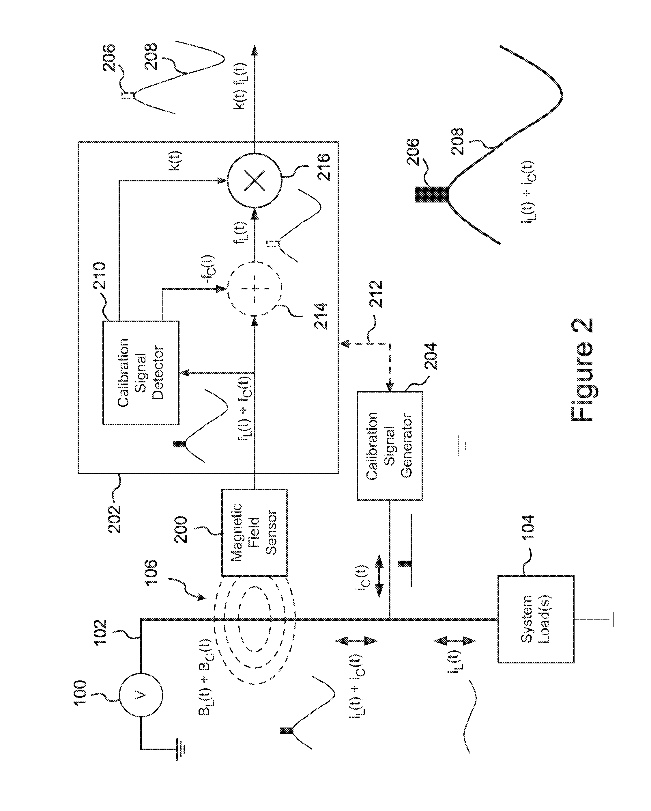
[0079]The present invention is a system for accurate, non-invasive measurement and monitoring of electrical current flowing through building wiring, or through any electrical circuit or circuits. With reference to FIG. 2, the system includes a remote current sensor 200, a receiver 202, and a calibration signal generator 204, or “CSG.”

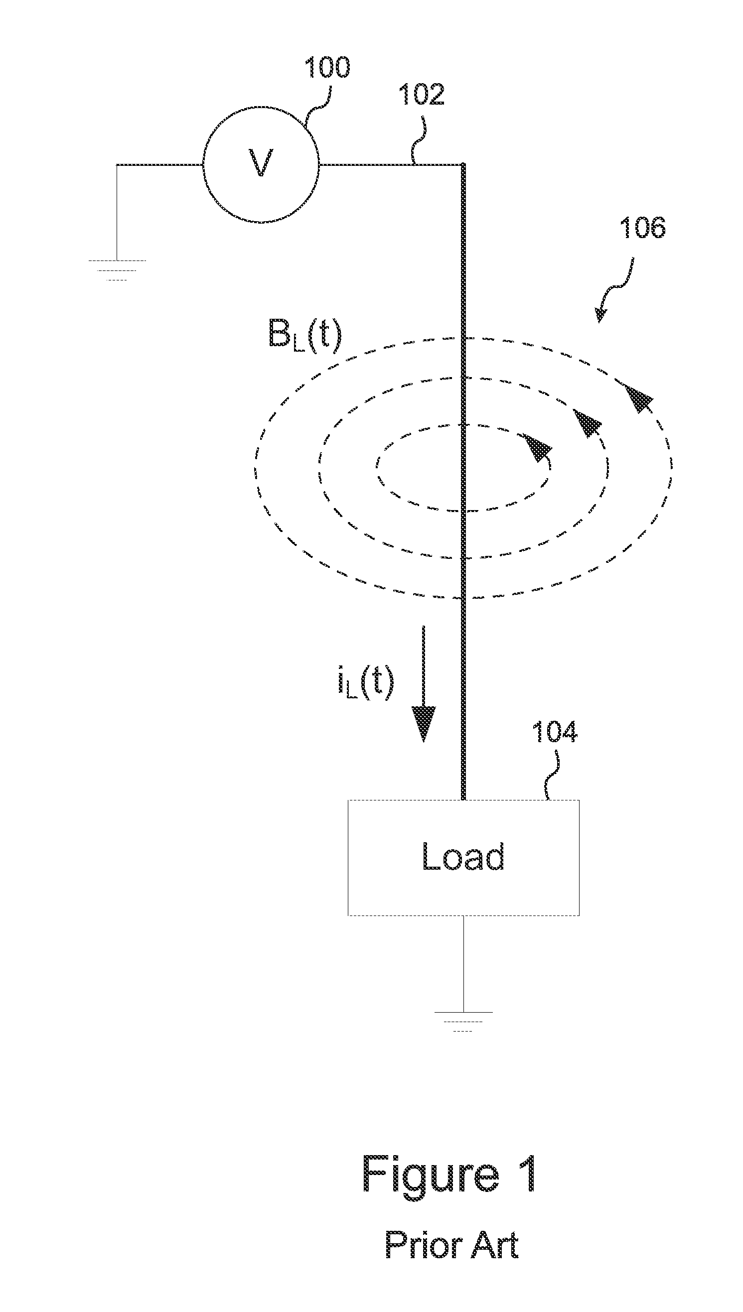
[0080]In embodiments, the sensor 200 is sensitive to the magnetic field generated by current flowing through a conductor. As discussed above with reference to FIG. 1, it is well known in the art that an electrical current flowing through a conductor 102 generates a proportional magnetic field 106 circulating around and orthogonal to the conductor 102. The direction and intensity of the magnetic field 106 is, respectively, dependent on the direction of current flow and the amount of current.

[0081]Devices for non-invasively measuring current in a conductor 102 by measuring the associated magnetic field can be broadly classified into two categories: “loop”...


PUM


Abstract

A system for accurate measurement and monitoring of AC or DC electrical current flowing through electrical conductors includes one or more current sensors, a receiver, and one or more calibration signal generators (“CSG's”) that can be plugged into outlets or otherwise coupled to the conductors so as to add automated, time-varying calibration signals to the conductors, such as current pulses or pulse patterns. The sensors are placed on a circuit breaker panel, around a cable, or otherwise near the conductors. The receiver distinguishes the calibration signals by their timing, pulse patterns, frequencies, or other time-varying features, uses their known amplitudes to calibrate the sensitivity of each sensor to each conductor, and determines the current flowing in each conductor. Among other applications, the invention can monitor building current usage, CO and data center power usage and distribution, and power line current leakage, and can calibrate invasive and/or non-invasive current sensors.

Description

RELATED APPLICATIONS[0001]This application claims the benefit of U.S. Provisional Application No. 61 / 361,122, filed Jul. 2, 2010, which is herein incorporated by reference in its entirety for all purposes.FIELD OF THE INVENTION[0002]The invention relates to electrical measurement apparatus, and more particularly, to apparatus for non-invasive sensing and monitoring of electrical current.BACKGROUND OF THE INVENTION[0003]Many studies have shown that both household and business consumers can dramatically reduce their power consumption if they can easily and continuously monitor their power usage. Estimates range from 10 to 20 percent savings for a typical household. In addition, many businesses and household consumers are strongly motivated to save energy so as to reduce consumption of hydrocarbons and reduce carbon emissions by reducing the amount of power that must be generated by electricity providers using coal and other hydrocarbon energy sources.[0004]Monitoring of power usage ca...

Claims


Application Information

Patent Timeline
IPC IPC(8): G01R35/00
CPCG01R15/18G01R15/20G01R15/148G01R15/14G01R35/005
Inventor REYNOLDS, BRETT S.
Owner REYNOLDS BRETT S
Why Eureka
Try Eureka