
Device and method for driving liquid crystal display device

Active Publication Date: 2012-01-05
LG DISPLAY CO LTD
View PDF22 Cites 8 Cited by
  • Summary
  • Abstract
  • Description
  • Claims
  • Application Information

AI Technical Summary

Benefits of technology

[0011]An object of the present invention is to provide a device and method for driving a liquid crystal display device, which is capable of improving image quality and reducing power consumption by varying a light emission region of a backlight unit according to brightness characteristics of a display image.
[0021]The irradiating of the light to the liquid crystal panel may include divisionally setting the driving regions of the backlight using the divisional driving region information and the at least one dimming control signal, and controlling on / off times of the set driving regions so as to control the amount of light supplied to the liquid crystal panel.
[0023]In a device and method for driving the liquid crystal display device according to the embodiment of the present invention, it is possible to display a lifelike image by varying light emission regions of a backlight unit according to the brightness characteristics of a display image so as to differentiate the brightness degrees of the divided light emission regions. In a divisional driving region in which light does not need to be emitted based on the brightness distribution of the display image, power is not consumed. Accordingly, it is possible to reduce power consumption of the liquid crystal display device.

Problems solved by technology

However, since the plurality of LED groups generates a constant brightness or the brightnesses of the plurality of LED groups are equally varied, power consumption may be increased.
Thus, power consumption is increased.
In addition, in the related art, since the brightness of the backlight is kept constant or constantly varied, a lifelike image may not be displayed.

Method used


Image

  • Device and method for driving liquid crystal display device
  • Device and method for driving liquid crystal display device
  • Device and method for driving liquid crystal display device

Examples


Embodiment Construction

[0031]Hereinafter, a device and method for driving a liquid crystal display device according to an embodiment of the present invention will be described in detail with reference to the accompanying drawings.

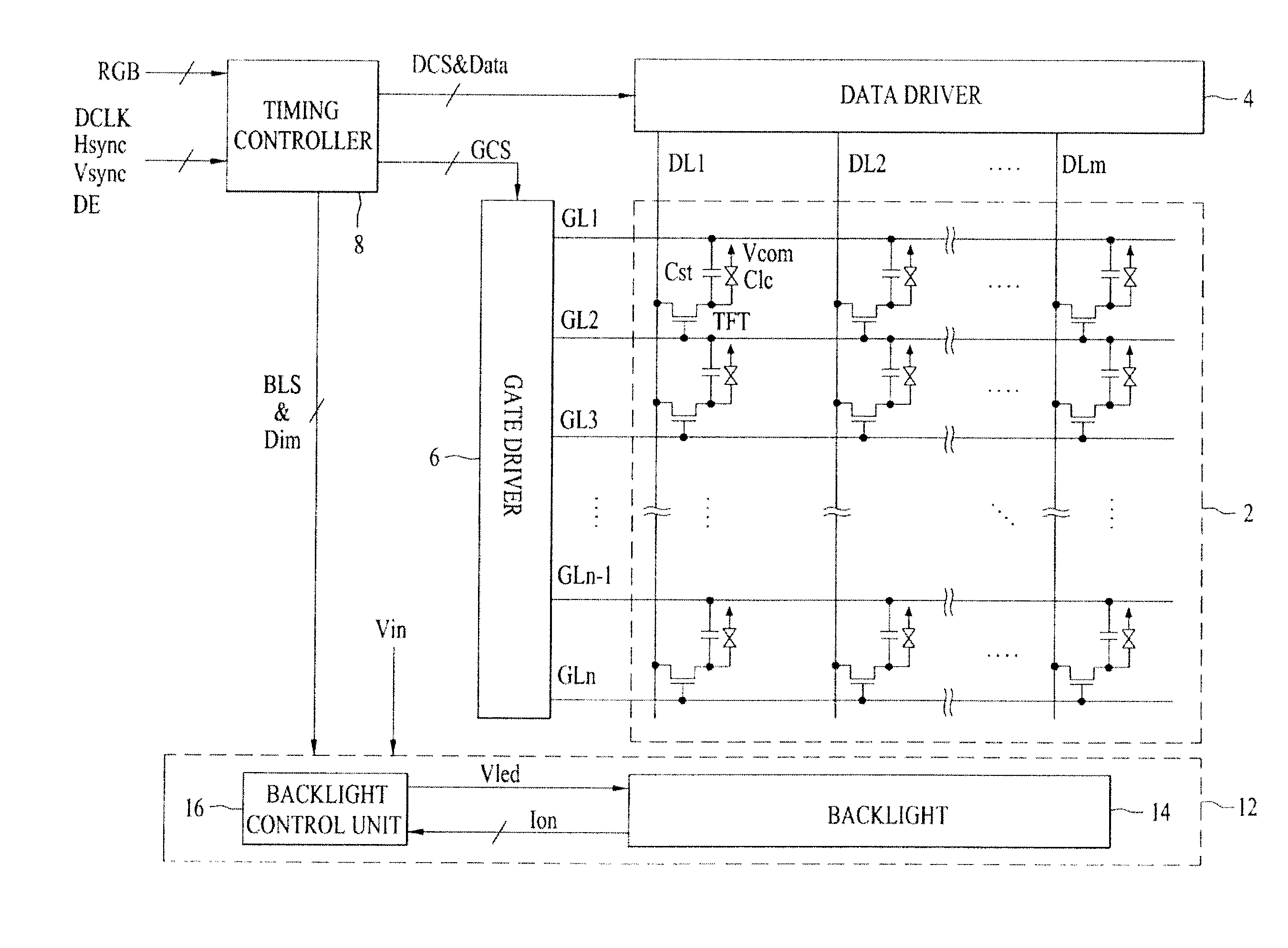
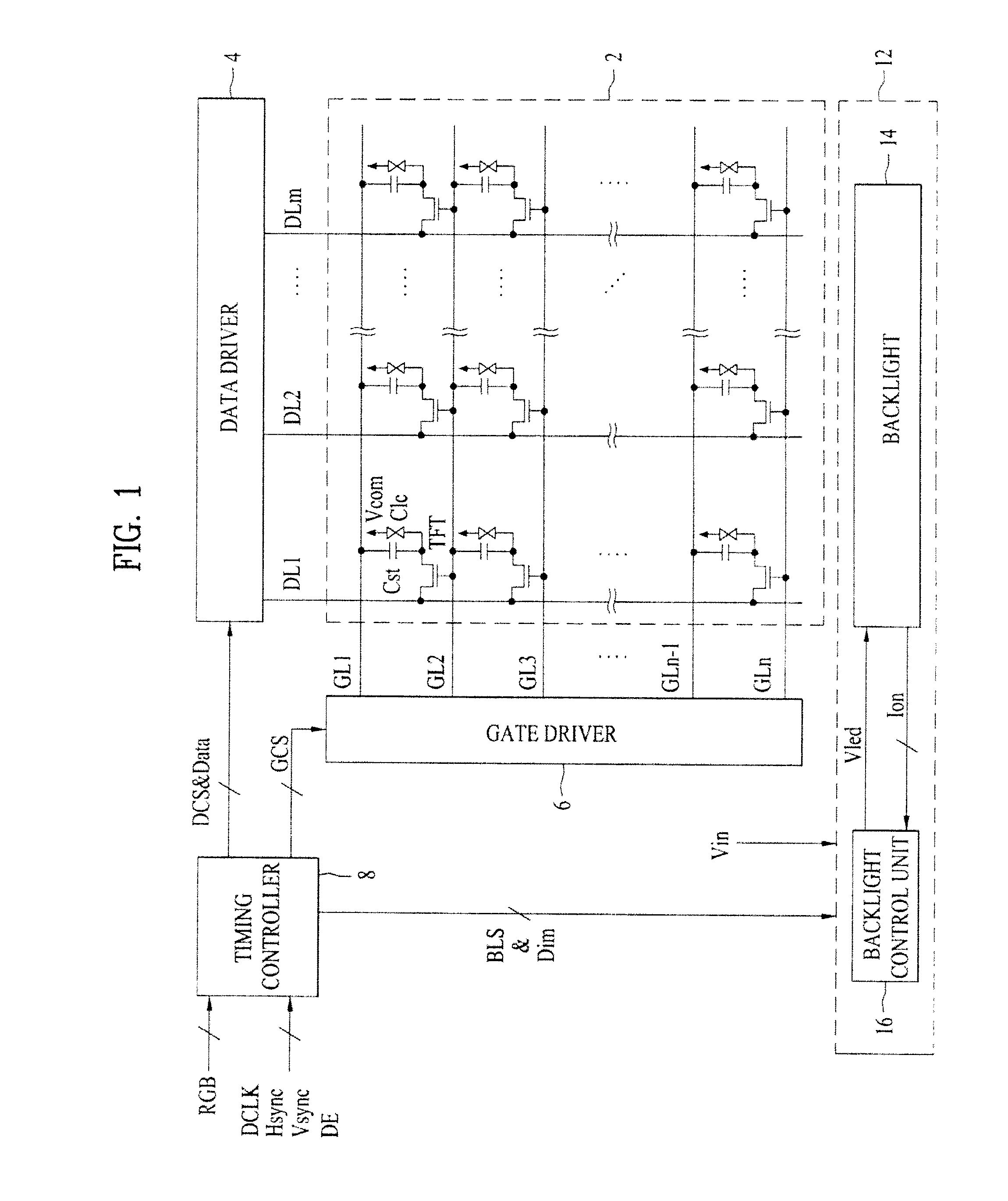
[0032]FIG. 1 is a diagram showing the configuration of a device for driving a liquid crystal display device according to an embodiment of the present invention.

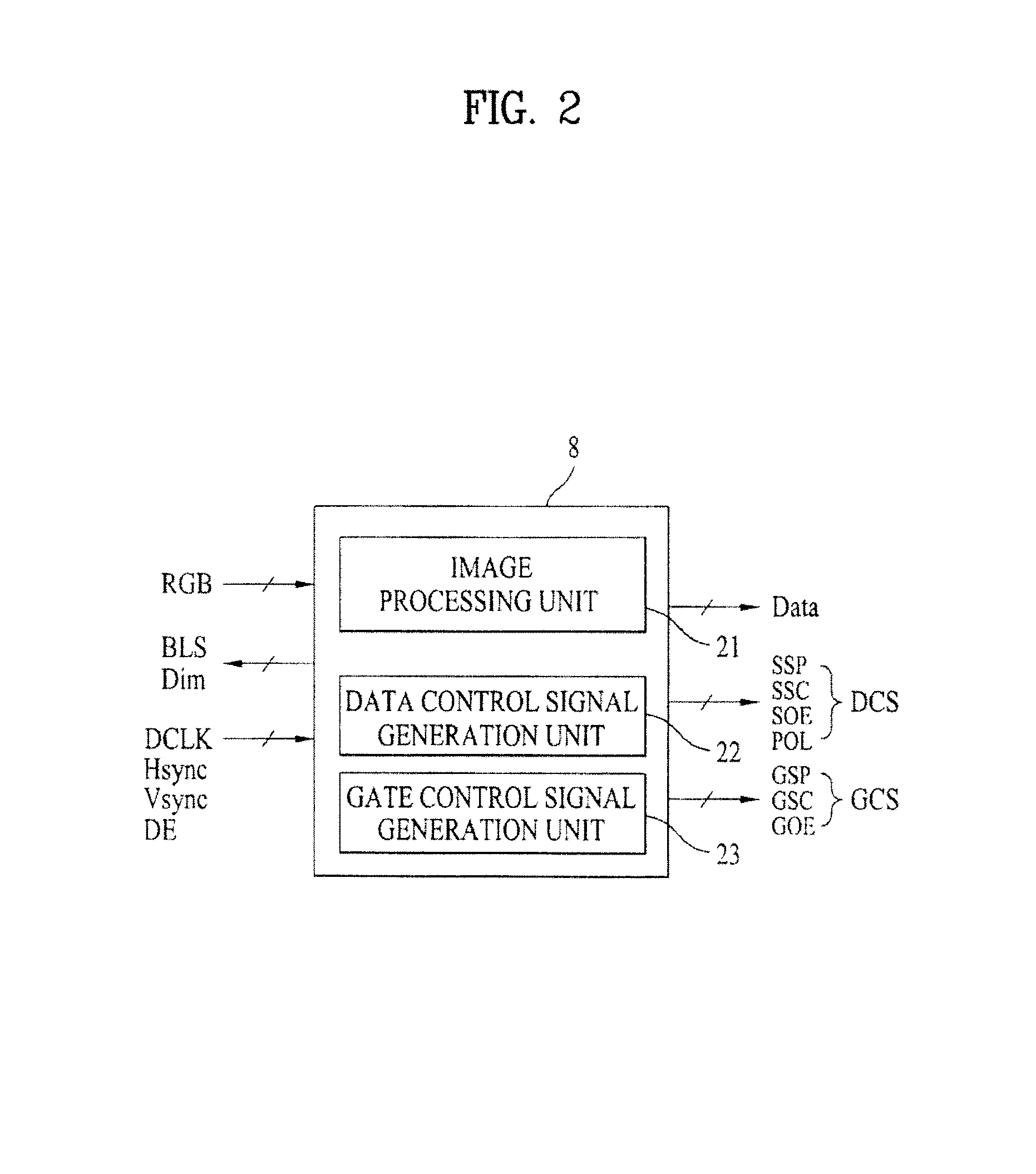
[0033]First, the device for driving the liquid crystal display device shown in FIG. 1 includes a liquid crystal panel 2 which includes a plurality of pixel regions and displays an image; a plurality of panel drivers 6 and 4 for driving gate and data lines GL1 to GLn and DL1 to DLm of the liquid crystal panel 2; a timing controller 8 for generating gate and data control signals GCS and DCS so as to control the plurality of panel drivers 6 and 4 and analyzing a brightness distribution of externally input image data RGB so as to set the number of divisional driving regions of a backlight 14, and generating and outputting a di...


PUM


Abstract

A device and method for driving a liquid crystal display device, which is capable of improving image quality and reducing power consumption by varying a light emission region of a backlight unit according to brightness characteristics of a display image, is disclosed. The driving device includes a liquid crystal panel, panel drivers, a timing controller for generating control signals to control the panel drivers, analyzing a brightness distribution of externally input image data to set the number of divisional driving regions of a backlight, and generating a dimming control signal to control the brightness of each of the divisional driving regions, and a backlight unit for divisionally setting the driving regions of the backlight according to the number of divisional driving regions and the dimming control signal and driving the driving regions according to the dimming control signal to irradiate light to the liquid crystal panel.

Description

[0001]This application claims the benefit of Korean Patent Application No. 10-2010-0063348, filed on Jul. 1, 2010, which is hereby incorporated by reference as if fully set forth herein.BACKGROUND OF THE INVENTION[0002]1. Field of the Invention[0003]The present invention relates to a liquid crystal display device, and more particularly, to a device and method for driving a liquid crystal display device, which is capable of improving image quality and reducing power consumption by varying a light emission region of a backlight unit according to brightness characteristics of a display image.[0004]2. Discussion of the Related Art[0005]With increasing adoption of information technology, demands for an image display device have been variously increased. Recently, a flat panel display device such as a Liquid Crystal Display (LCD) device, a Field Emission Display (FED) device, a Plasma Display Panel (PDP) device, or a Light Emitting Diode (LED) display device is mainly used.[0006]An LCD de...

Claims


Application Information

Patent Timeline
IPC IPC(8): G09G3/36G09G5/10
CPCG09G3/2096G09G3/3426G09G2320/0646G09G2320/064G09G3/3648
Inventor CHO, SOON-DONGKIM, JUNG-JAELEE, SANG-UK
Owner LG DISPLAY CO LTD
Learn More