Method for Encoding Data Symbols with Implicitly Embedded Pilot Symbols in Resource Blocks for Wireless Networks

a technology of wireless network and pilot symbol, applied in diversity/multi-antenna system, multi-frequency code system, transmission path sub-channel allocation, etc., can solve the problem that the fixed number of pilot symbols might not be sufficient to estimate a rapidly varying channel, waste power, time and bandwidth (frequency) that could otherwise be used to increase the data rate, and separate transmission of pilot symbols, etc. problem, to achieve the effect of improving the overall network spectral efficiency, improving channel estimation accuracy, and saving resources

Active Publication Date: 2012-01-05
MITSUBISHI ELECTRIC RES LAB INC
View PDF2 Cites 14 Cited by
  • Summary
  • Abstract
  • Description
  • Claims
  • Application Information

AI Technical Summary

Benefits of technology

[0010]As a result, there is no need to allocate valuable resources, such as transmission time and bandwidth, to explicitly carry known pilot symbols as in the prior art. This leads to significant savings in time and bandwidth resources, thereby improving the overall network spectral efficiency.
[0011]Because all of the data symbols in our ERB design contain a portion of the implicit pilot symbols, the invention improves channel estimation accuracy, and thereby improves reliability and performance over channels with high variability and efficient resource utilization over channels with little variability.

Problems solved by technology

However, separate transmission of the pilot symbols wastes power, time and bandwidth (frequency) that could otherwise be used to increase the data rate.
More importantly, a fixed number of the pilot symbols might not be sufficient to estimate a rapidly varying channel.
It is also inefficient to estimate a channel that does not vary appreciably with a fixed number of pilot symbols.
Because many different configurations are possible in placing pilot symbols and data symbols in a time-frequency resource block (RB), in a non-overlapping fashion, the consequence is that design and implementation of conventional RBs are less flexible.

Method used


Image

  • Method for Encoding Data Symbols with Implicitly Embedded Pilot Symbols in Resource Blocks for Wireless Networks
  • Method for Encoding Data Symbols with Implicitly Embedded Pilot Symbols in Resource Blocks for Wireless Networks
  • Method for Encoding Data Symbols with Implicitly Embedded Pilot Symbols in Resource Blocks for Wireless Networks

Examples


Embodiment Construction

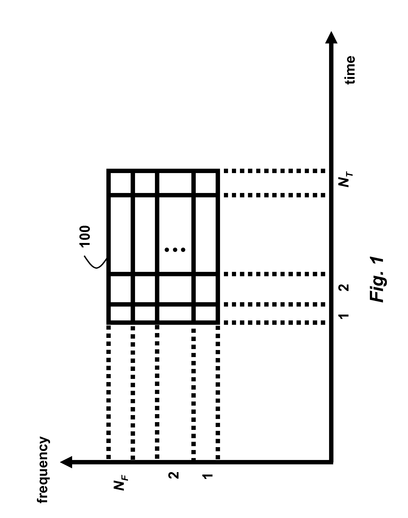
[0025]FIG. 1 shows an embedded resource block (ERB) 100 according to embodiments of our invention. In a two-dimensional time-frequency plane, the ERB is described by time-frequency resource units spanned by NT consecutive data symbols over NF consecutive frequency (or sub-carrier or sub-channel) tones. Each symbol is selected from a set of modulation constellations and represents data to be transmitted. It is noted that different symbols can be selected from different constellations. Thus, effectively, the symbols can be selected from a set of one or more of modulation constellations.

[0026]In wireless communications with orthogonal frequency-division multiplexing (OFDM) modulation, the channel coherence time is defined as the number of consecutive OFDM symbols during which the channel remains constant. The channel coherence bandwidth is defined as the number of consecutive subcarriers over which the channel remains constant.

[0027]The channel coherence (c) in the time-domain (T), in ...


PUM


Abstract

A set of data symbols is selected from a set of modulation constellation, and a sample-mean of the set of data symbols is determined. Each data symbol is first shifted by the sample-mean to obtain a shifted data symbol, and then the shifted symbol is multiplied by a first constant to obtain a scaled data symbol. A second constant is added to the scaled data symbol to obtain a mapped data symbol. The sample-mean is multiplied by a third constant to obtain a sample-mean mapped symbol. The set of mapped data symbols and the sample-mean mapped symbol are then transmitted as a resource block.

Description

FIELD OF INVENTION[0001]This invention relates generally to signal encoding in wireless communication networks, and more particularly to mapping data symbols selected from a set of modulation constellations onto data subcarriers with multiple transmitter antennas over multiple-input and multiple-output (MIMO) orthogonal frequency-division multiplexing (MIMO-OFDM) networks, and MIMO-OFDM-based relay-assisted cooperative communication networks.BACKGROUND OF INVENTION[0002]In wireless communication networks, orthogonal frequency division multiplexing (OFDM) and multiple-input and multiple-output (MIMO) transceivers can improve reliability for frequency-selective fading channels over wider transmission bandwidths, and also exploit frequency-selective scheduling gains in multi-user cellular (mobile) networks.[0003]Without requiring additional bandwidth, MIMO techniques provide an enormous increase in data rates needed to support ever expanding high performance wireless networks. Furtherm...

Claims


Application Information

Patent Timeline
Patent Type & Authority Applications(United States)
IPC IPC(8): H04L27/00H04L27/36
CPCH04L1/0606H04L1/0618H04L5/0023H04L2025/03426H04L25/0226H04L25/03343H04L27/345H04L5/0048
Inventor ANNAVAJJALA, RAMESHORLIK, PHILIP V.
Owner MITSUBISHI ELECTRIC RES LAB INC
Why Eureka
Try Eureka