Hydraulic Drive Apparatus for Construction Equipment

a technology of construction equipment and hydraulic drive, applied in the direction of servomotors, electrical control, instruments, etc., can solve the problems of not taking into account the work element of the working machine upon forced regeneration, and unforeseen situations, so as to improve safety

Active Publication Date: 2012-01-05
NIHON KENKI CO LTD
View PDF12 Cites 27 Cited by
  • Summary
  • Abstract
  • Description
  • Claims
  • Application Information

AI Technical Summary

Benefits of technology

[0018]According to the present invention, it is possible, as mentioned above, to prevent conducting forced regeneration even when all the work hydraulic actuators are in non-operated states, unless the work element has taken the proper attitude pre-specified as a safe attitude during forced regeneration. Therefore, the present invention can provide the working machine with improved safety during forced regeneration.

Problems solved by technology

However, what attitude a working element of the working machine should take upon forced regeneration is not taken into consideration as a condition.
It is, therefore, necessary to keep in mind that, even in a non-operated state in which all hydraulic actuators for driving a working machine are not operated, an unforeseen situation may arise and pressure oil may be fed to one or more of the hydraulic actuators.

Method used


Image

  • Hydraulic Drive Apparatus for Construction Equipment
  • Hydraulic Drive Apparatus for Construction Equipment
  • Hydraulic Drive Apparatus for Construction Equipment

Examples


first embodiment

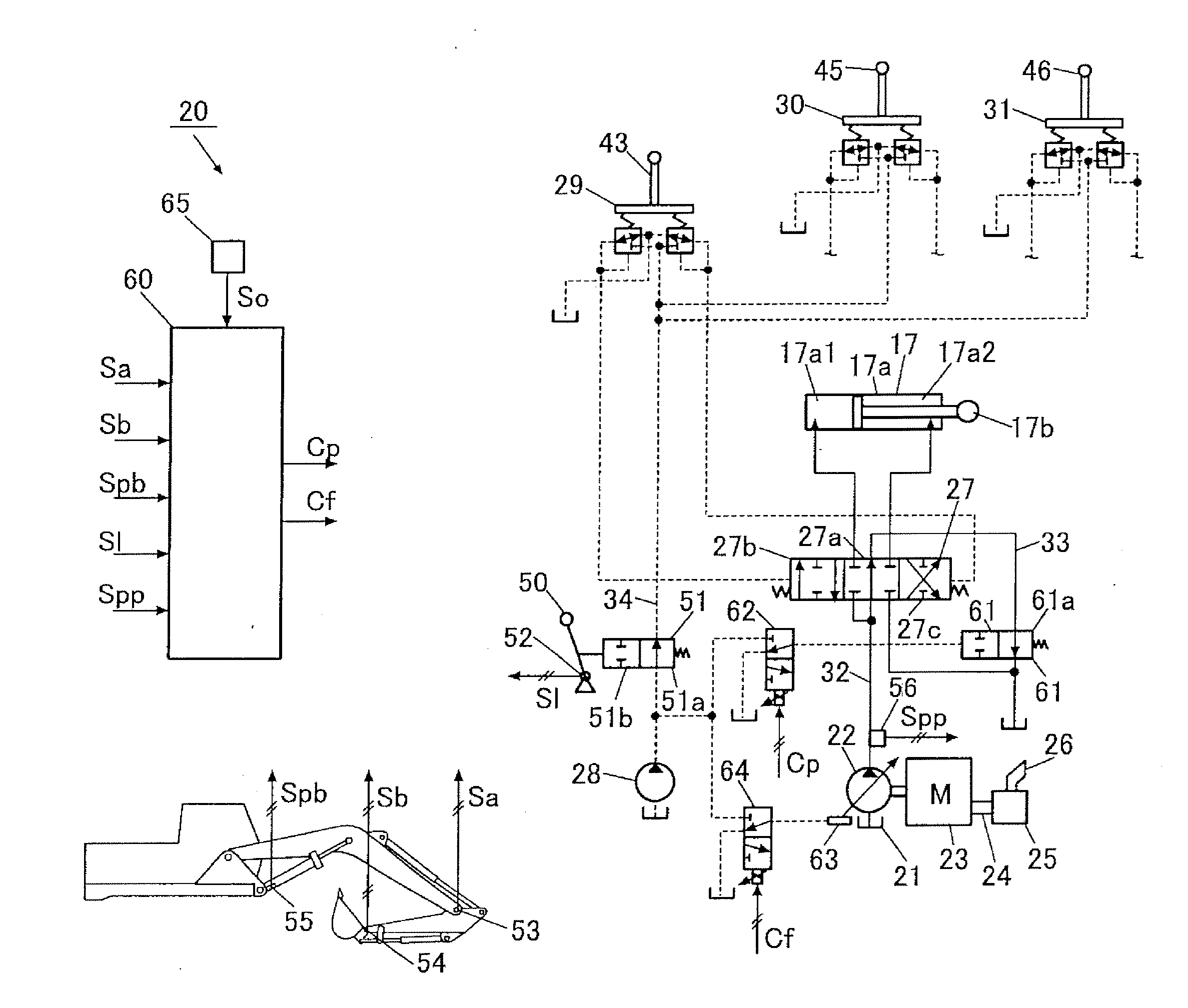
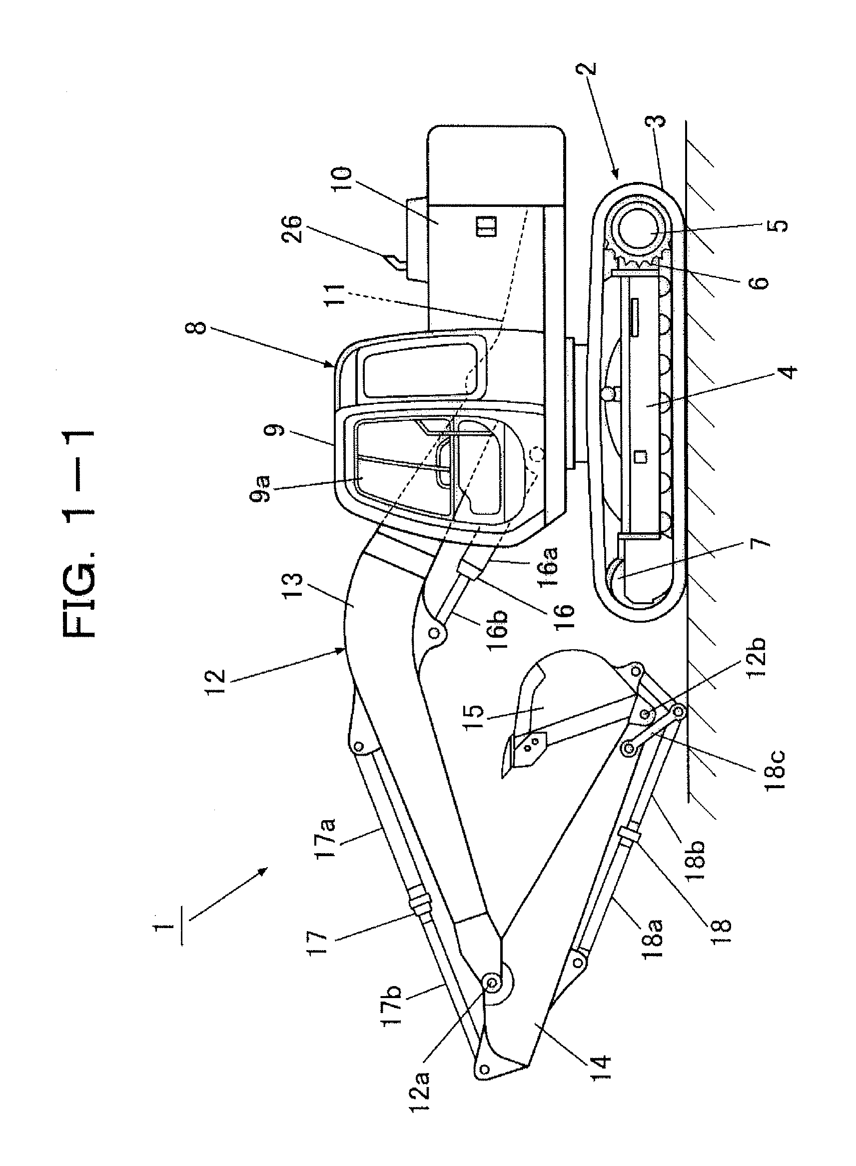
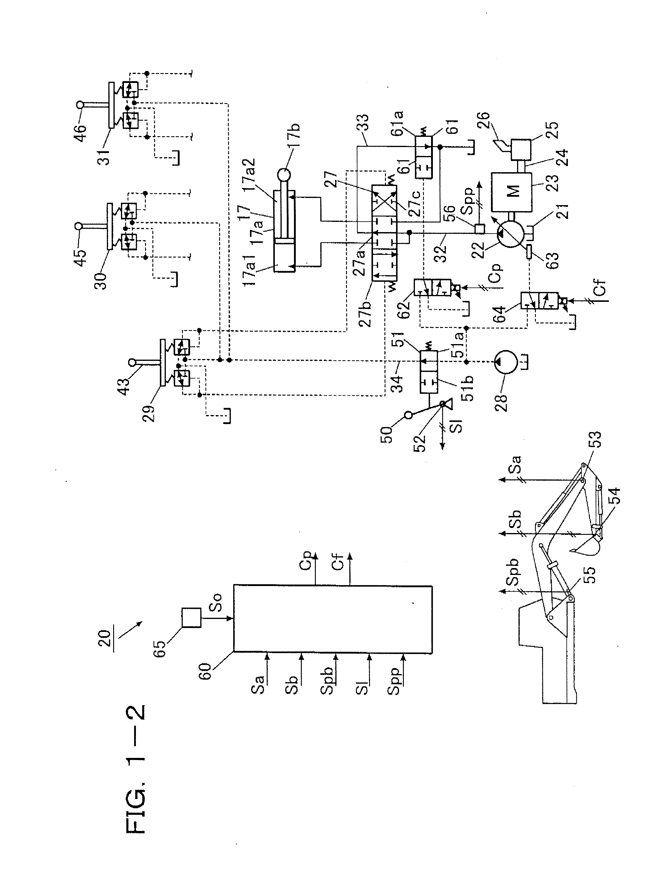
[0028]With reference to FIGS. 1-1 through 1-4, a description will be made about the first embodiment. FIG. 1-1 is a left side view of a crawler hydraulic excavator as a self-propelling working machine according to the first embodiment of the present invention. FIG. 1-2 is a hydraulic circuit diagram showing in a simplified form a hydraulic drive system arranged in the crawler hydraulic excavator shown in FIG. 1-1. FIG. 1-3 is a flow chart illustrating a flow of processing to be performed at a controller depicted in FIG. 1-2. FIG. 1-4 is a perspective view of the inside of an operator's cab of the crawler hydraulic excavator illustrated in FIG. 1-1, as viewed from front of and obliquely above an operator's seat.

[0029]As illustrated in FIG. 1-1, the crawler hydraulic excavator 1 (hereinafter simply called “the hydraulic excavator 1”) is provided with a travel base 2 which runs by driving crawler tracks 3, a revolving upperstructure 8 swingably connected to the travel base 2, and a fro...

second embodiment

[0066]With reference to FIGS. 2-1 through 2-4, a description will be made about the second embodiment. FIG. 2-1 is a left side view of a wheel hydraulic excavator as a self-propelling working machine according to the second embodiment of the present invention. FIG. 2-2 is a hydraulic circuit diagram showing in a simplified form a hydraulic drive system arranged in the wheel hydraulic excavator illustrated in FIG. 2-1. FIG. 2-3 is a flow chart illustrating a flow of processing to be performed at a controller shown in FIG. 2-2. FIG. 2-4 is a perspective view of the inside of an operator's cab of the wheel hydraulic excavator illustrated in FIG. 2-1, as viewed from front of and obliquely above an operator's seat. Among elements and signals illustrated in FIGS. 2-1 through 2-4, like elements and signals to the corresponding ones illustrated in FIGS. 1-1 and 1-2 are designated using like reference signs.

[0067]A wheel hydraulic excavator 101 (hereinafter called “the hydraulic excavator 10...


PUM


Abstract

A hydraulic drive system for a working machine provides improved safety during forced regeneration. Upon input of a forced regeneration command signal from a forced regeneration switch, a controller detects non-operated states of all hydraulic actuators such as an arm cylinder arranged on a hydraulic excavator based on a lock detection signal from a gate lock detection switch, and also an attitude of a front working mechanism. The attitude is proper from the standpoint of safety. The detection is based on an arm angle signal from an arm angle sensor, a bucket angle signal from a bucket angle sensor and a boom pressure signal from a boom pressure sensor. Taking the detection of the non-operated states and proper attitude as conditions, the controller outputs control signals to a boosting proportional solenoid valve and flow-rate controlling, proportional solenoid valve to make a forced regenerator conduct forced regeneration.

Description

TECHNICAL FIELD[0001]The present invention relates to a hydraulic drive system for a working machine such as a hydraulic excavator. The hydraulic drive system can be adopted in the working machine, is provided with an exhaust gas purification device for capturing, by a filter, particulate matter in exhaust gas produced in an engine (prime mover), and burns off particulate matter deposited on the filter to conduct so-called forced regeneration.BACKGROUND ART[0002]Conventionally, a hydraulic drive system for a working machine has been designed to permit detecting clogging of a filter in an exhaust gas purification device. When the working machine is in a non-operated state at the time of detection of clogging, the hydraulic drive system is set to automatically conduct forced regeneration. This forced regeneration conducted by the hydraulic drive system increases the delivery flow rate and delivery pressure of a hydraulic pump to increase the engine output, whereby the temperature of e...

Claims


Application Information

Patent Timeline
Patent Type & Authority Applications(United States)
IPC IPC(8): E02F9/22F01N3/023E02F3/43
CPCE02F9/226E02F9/2282E02F9/2285E02F9/2296E02F9/265Y02T10/26F02D41/029F02D2041/026F02D2200/604F15B11/024F15B21/14F02D41/0245Y02T10/12
Inventor HAGIWARA, NAOKINAKAMURA, TSUYOSHISATO, KENSUKEOKANO, YASUOISHIKAWA, KOUJIEZAWA, MASANORI
Owner NIHON KENKI CO LTD
Why Eureka
Try Eureka