Dry vacuum pump

a vacuum pump and vacuum pump technology, applied in the field of dry vacuum pumps, can solve the problems of increased operating temperature, brittleness of frictional ring seals, and insufficient safety measures, and achieve the effect of increasing the service li

Active Publication Date: 2012-01-05
PFEIFFER VACUUM GMBH
View PDF4 Cites 6 Cited by
  • Summary
  • Abstract
  • Description
  • Claims
  • Application Information

AI Technical Summary

Benefits of technology

[0009]It is one of the aims of the present invention to propose a dry type vacuum pump comprising a lubricant-sealing device, mounted between a lubricated support bearing and a pumping stage, the service life of which is increased.
[0018]Thus, when the lubricant mist is drawn from the lubricated support bearing to the pumping stage, the lubricant is deflected by the lubricant deflector into the lubricant return channel through the effect of centrifugal force until it gets poured into the reserve of liquid lubricant of the second isolated reservoir. Then, during the pressure-balancing phases when the pressure of the lubricated support bearing is greater than the pressure of the pumping stage, the lubricant that has fallen to the bottom of the reservoir into the second reserve of lubricant, at a level lower than that of the opening of the lubricant return channel, cannot rise in this channel. On the contrary, “dry” gas, i.e. lubricant-free gas, situated in the second reservoir above the level of lubricant liquid, will fill the lubricant return channel and restore the balancing of the pressures on either side of the sealing device. The separation of the second reservoir thus prevents the misty lubricant air contained in the oily environment of the lubricated support bearing in operation from entering the lubricant return channel.
[0021]With this calibration of the conductance values, when the pressure drops in the pumping stage, it drops more quickly in the first volume comprising the lubricated support bearing than in the second volume in the isolated second reservoir. The second volume then preserves a slight excess pressure relatively to the first volume. The dry gas will then rush through the lubricant return channel and get accelerated therein up to the inlet of the lubricant return channel thus forming a barrier of dry gas at the lubricant deflector. This process encourages an acceleration of the gas stream in the lubricant return channel from the second volume to the lubricant deflector rather than from the first volume to the second volume.

Problems solved by technology

However, this safety measure could prove to be inadequate.
The intensification of production output rates is leading to increased operating temperatures for vacuum pumps, and this can make the frictional ring seal more brittle.
Furthermore, the increase in the repetition of pressure variations on either side of the frictional ring seal, which can be associated with corrosiveness in the lubricant that has gone through the lubricant deflector, can cause a premature wearing out of the frictional ring seal and require servicing at closer intervals, each intervention involving the stoppage of the semiconductor manufacturing installations and stoppage of the vacuum pump, and this is very costly.

Method used


Image

  • Dry vacuum pump
  • Dry vacuum pump
  • Dry vacuum pump

Examples


Embodiment Construction

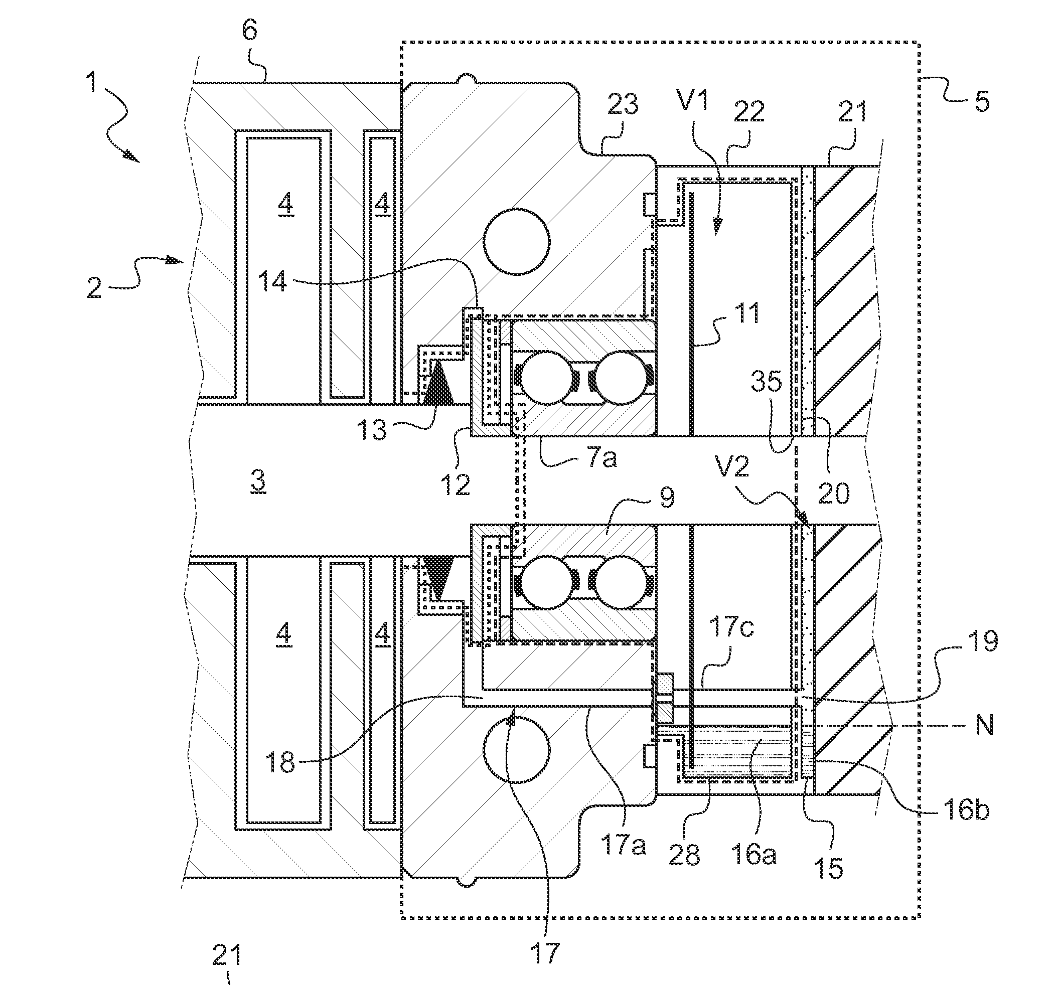
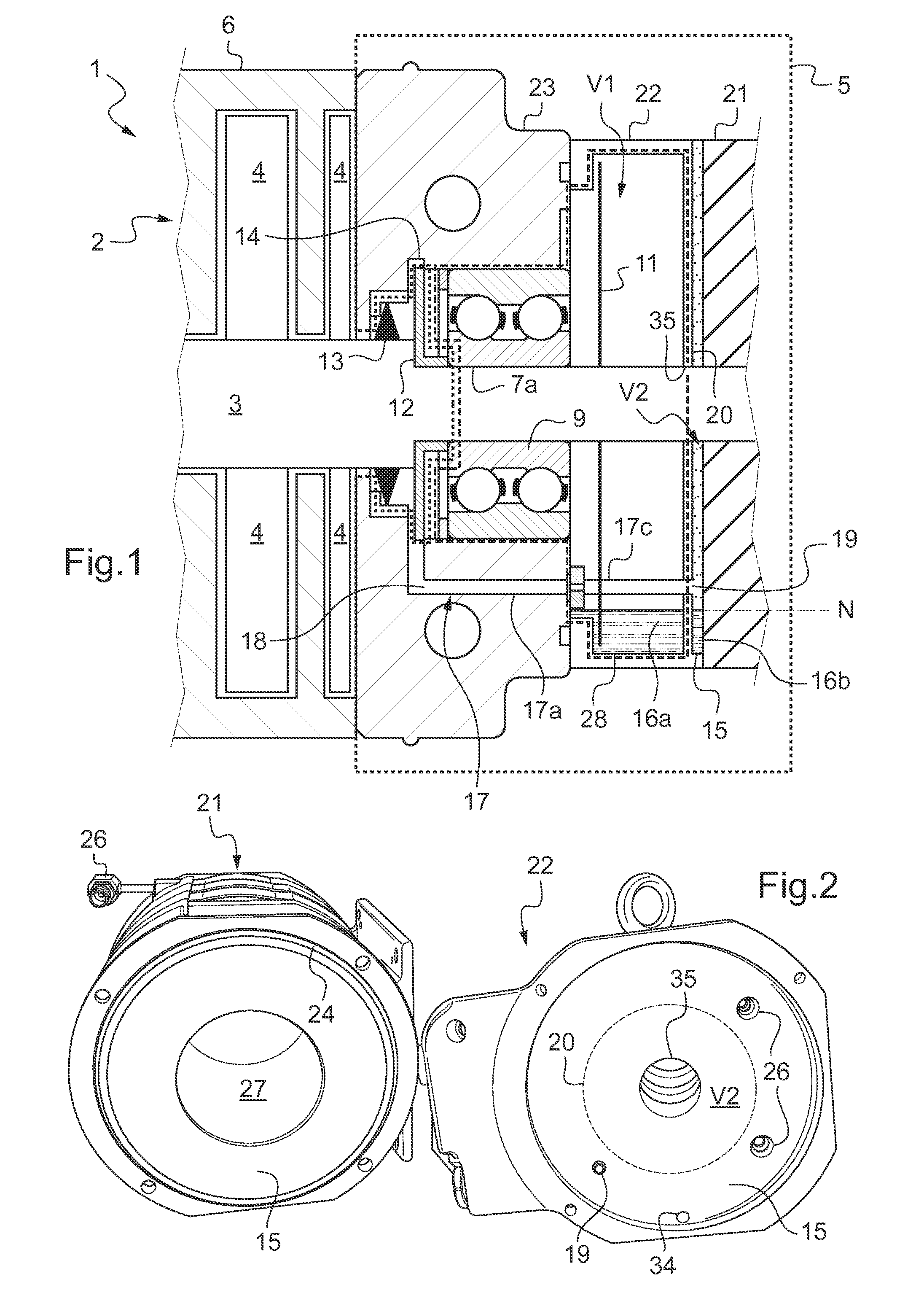
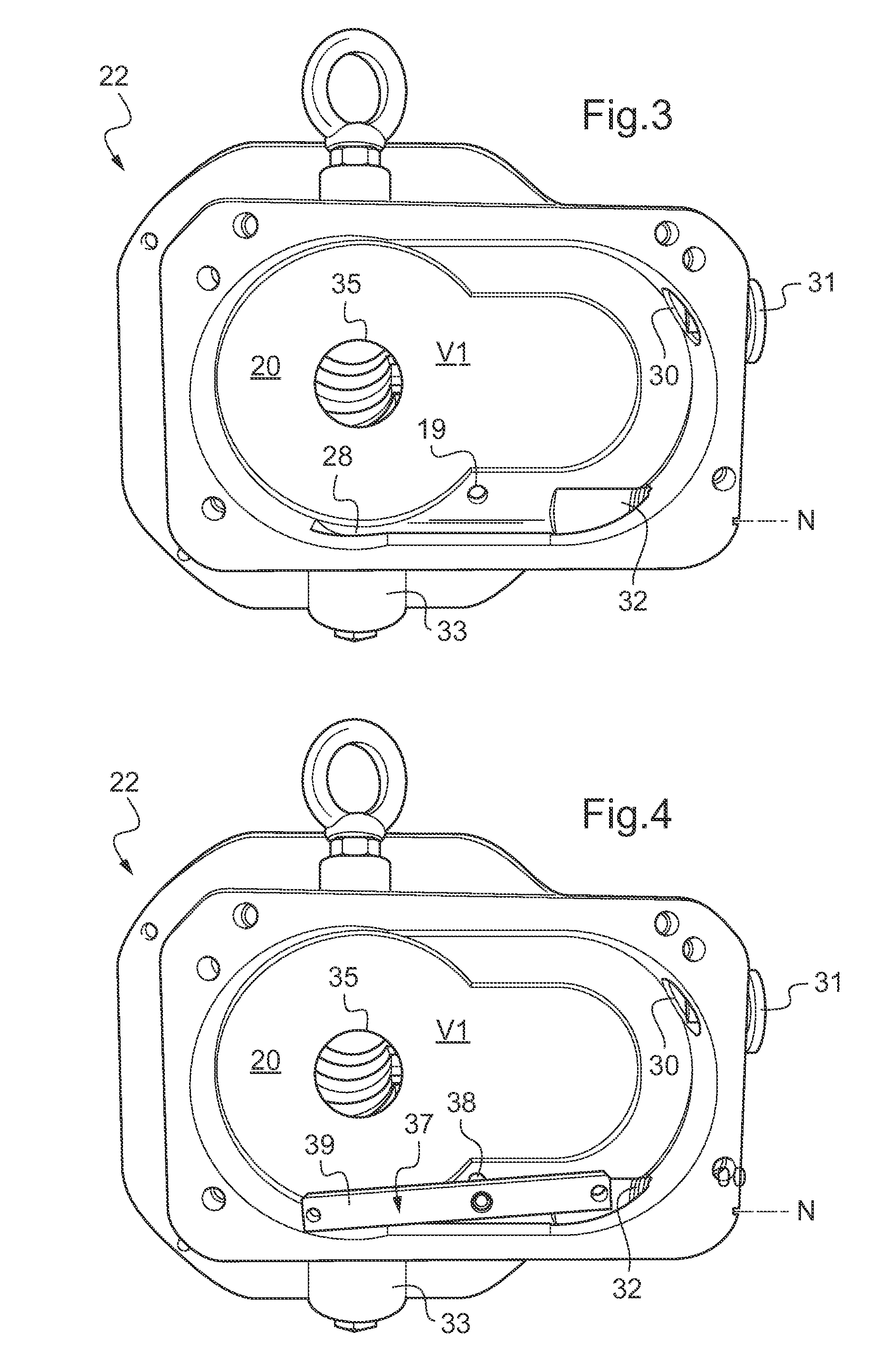
[0034]FIGS. 1 to 6 illustrate an exemplary embodiment of a dry type vacuum pump having two Roots type rotary lobe shaft. Naturally, the invention can also be applied to other types of dry-type vacuum pumps such as “claw”, spiral or screw type pumps or pumps based on any other similar principle.

[0035]The vacuum pump 1 has one or more series-mounted pumping stages 2 in which a gas to be pumped circulates from an admission inlet to a delivery outlet (not shown). The rotary shafts 3 (only one can be seen in FIG. 1) extend into the pumping stage 2 by rotary lobe rotors 4 and are driven on the delivery stage side in a motor drive compartment 5 of the vacuum pump 1. The pumping stage 2 is said to be “dry” because during operation the rotors 4 rotate inside the casing 6 in opposite directions without any mechanical contact between the rotors 4 and the casing 6 of the vacuum pump 1, enabling a total absence of lubricant.

[0036]The vacuum pump works horizontally as shown in FIG. 1, i.e. during...


PUM


Abstract

The invention pertains to a dry-type vacuum pump comprising:at least one pumping stage (2),at least one rotary shaft (3) supported by a lubricated support bearing (7a, 7b)at least one lubricant deflector (12) and one ring seal (13) mounted on the rotary shaft, the ring seal (13) being mounted between the lubricant deflector (12) and the pumping stage (2), the lubricant deflector being mounted between the lubricated support bearing (7a, 7b) and the ring seal,a first reservoir (28) containing a first reserve of liquid lubricant (16a), said first reservoir (28) being in communication with the lubricated support bearing (7a, 7b) in a first volume (V1),a lubricant splashing unit mounted on the rotary shaft (3) in the first reservoir (28), one end of the lubricant splashing unit being bathed in the first reserve of liquid lubricant (16a),The vacuum pump has a second reservoir (15) comprising a second reserve of liquid lubricant (16b), the second reservoir (15) being separated from the first reservoir (28) by a separation wall (20) having a communication aperture (34) that puts the first and the second reserves of liquid lubricant (16a, 16b) into communication. A lubricant return channel (17) having one inlet (18) situated so as to be facing said lubricant deflector (12) opens into the second volume (V2) of the second reservoir above the second reserve of liquid lubricant (16b).

Description

BACKGROUND OF THE INVENTION[0001]1. Field of the Invention[0002]The present invention pertains to a dry type vacuum pump comprising a device for sealing against lubricants mounted between a lubricated support bearing and a pumping stage. The invention can be applied especially to a Roots or claw dry type vacuum pump comprising two rotary lobed shafts or again a spiral type or screw type pump or a pump working on another similar principle.[0003]These pumps generally comprise one or more series-mounted pumping stages in which a gas to be pumped flows between an admission intake and a delivery outlet. Prior-art vacuum pumps include rotary lobe pumps known as bi-lobe or tri-lobe Roots pumps and double claw pumps also known as “claw” pumps.[0004]A rotary lobe pump comprises two rotors of identical profiles rotating in opposite directions inside a stator. During rotation, the gas to be pumped is trapped in the free space contained between the rotors and the stator, and is driven by the ro...

Claims


Application Information

Patent Timeline
Patent Type & Authority Applications(United States)
IPC IPC(8): E21B43/12
CPCF01C19/005F04C18/12F04C25/02F04C27/009Y10S418/01F04C29/028F04C2220/12F04C2240/809F04C29/021F04C18/00F04C18/02F04C18/04F04C18/18F04C27/00F04C29/00F04C29/02F04C29/025
Inventor CROCHET, STEPHANE
Owner PFEIFFER VACUUM GMBH
Why Eureka
Try Eureka