LED centralized DC power supply system and operating methods thereof

a power supply system and centralized technology, applied in the field of power supply systems, can solve the problems of difficult realization of unified light adjustment of a plurality of leds, large size and higher cost, and high cost and service life, and achieve the effect of less line loss, convenient maintenance of power supply, and effective control of line loss

Active Publication Date: 2013-08-15
SOUTH CHINA UNIV OF TECH
View PDF18 Cites 12 Cited by
  • Summary
  • Abstract
  • Description
  • Claims
  • Application Information

AI Technical Summary

Benefits of technology

[0016]Redundancy supply of N+1 power supplies is realized through the N+1 three-phase PWM rectifier modules, so that the whole LED system is very reliable, and the maintenance of the power supply is very convenient. Each of the N+1 three-phase PWM rectifier modules has three-phase AC input ends which are respectively and correspondingly connected with the three-phase AC input interface (Ua, Ub, Uc) from top to bottom, has a positive (+) output end connected with the positive output bus, has a negative (−) output end connected with the negative output bus, has a three-phase PWM rectifier which realizes adjustable output voltage and PFC (power factor correction) through PWM adjustment of the module.
[0017]The power supply device being installed in the center of the positive and negative output bus can effectively control line loss, so the line loss is less.

Problems solved by technology

Such power supplying mode has the following problems: firstly, the position and radiator of the power supply should be considered in the lamp design, which results in larger size and higher cost, hence the lamp design is limited by the power supply; secondly, the whole lamp will be out of use once the power supply is damaged, which causes high cost and short service life; finally, unified light adjustment of a plurality of LEDs is difficult to be realized.

Method used


Image

  • LED centralized DC power supply system and operating methods thereof
  • LED centralized DC power supply system and operating methods thereof
  • LED centralized DC power supply system and operating methods thereof

Examples


Embodiment Construction

[0022]The preferred embodiment of the invention is further described by combining the drawings and is in no way intended to limit the invention.

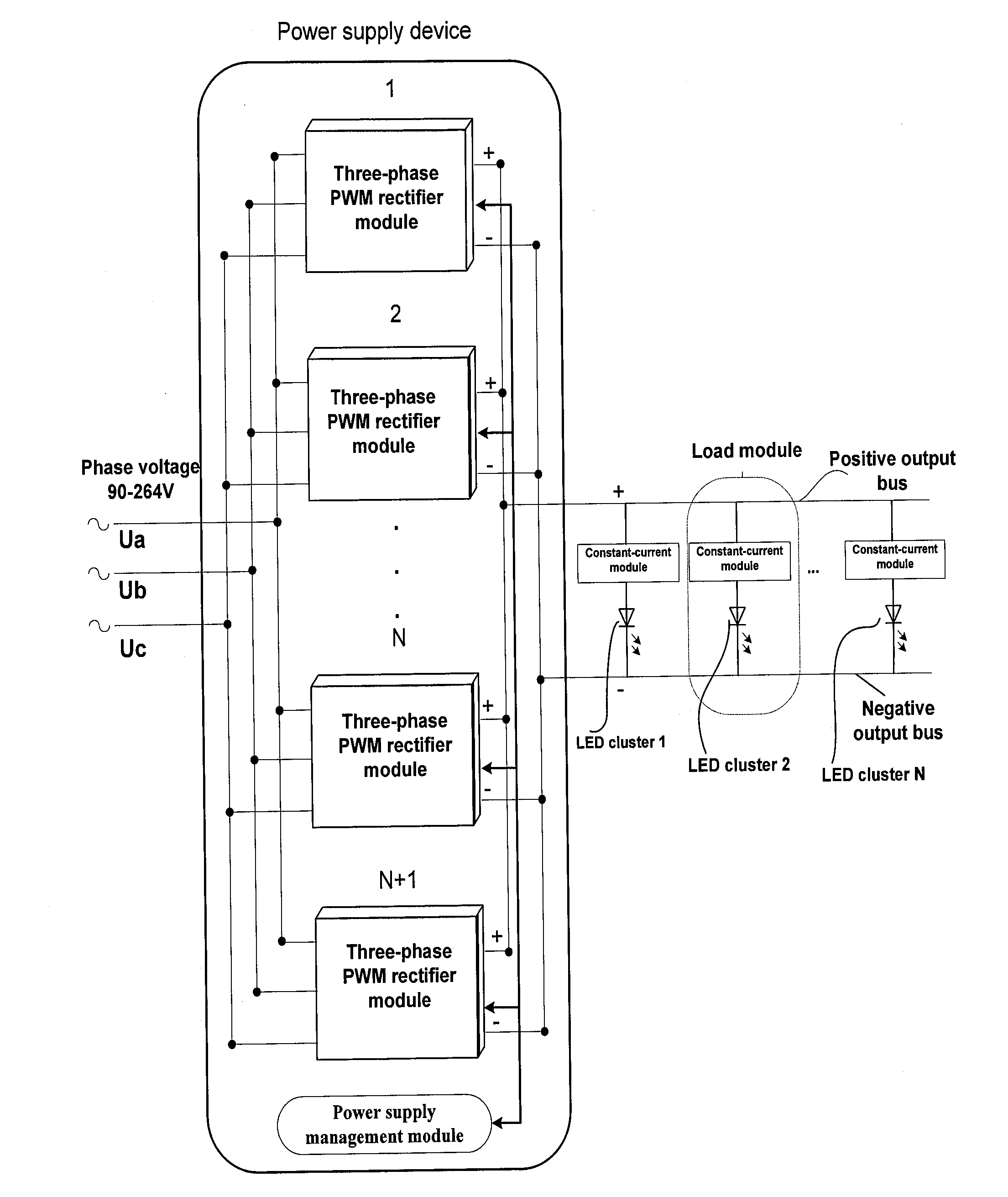
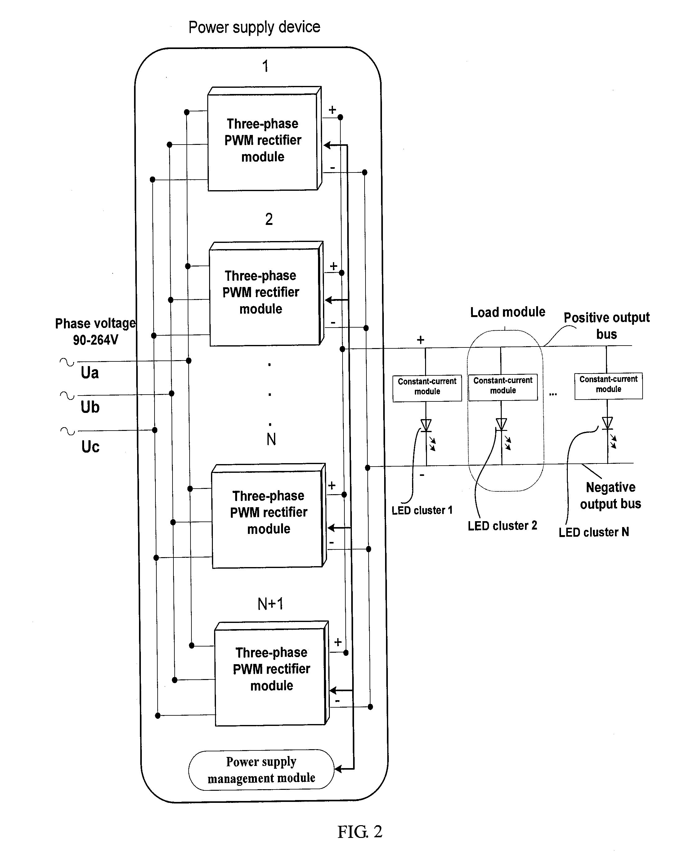
[0023]In FIG. 2, the invention provides an LED centralized DC power supply system, which comprises: a three-phase AC input interface; a power supply output interface having a positive output bus and a negative output bus; N+1 three-phase PWM rectifier modules, wherein each of N+1 three-phase PWM rectifier modules has a three-phase AC input end that is connected with said three-phase AC input interface, has a positive output end that is connected with said positive output bus, and has a negative output end that is connected with said negative output bus, wherein N is a natural number; LED cluster loads which are connected between said positive output bus and said negative output bus; and a power supply management module, connected with each of said N+1 three-phase PWM rectifier modules, detecting status of input and output of the power supply...


PUM


Abstract

The invention provides a light emitting diode (LED) centralized DC (direct-current) power supply system and operating methods thereof. The proposed DC power supply system comprises a three-phase AC (alternating-current) input interface, a DC power supply output interface, N+1 three-phase PWM (pulse width modulation) rectifier modules, LED cluster loads and a power supply management module. The proposed operating methods are described as following: the power supply management module adjusts the duty ratio of the three-phase PWM rectifier modules, based on the control signals formed by synthesizing the information about voltage and current of the positive and negative output buses, the three-phase AC input ends, control signals and output of the three-phase PWM rectifier modules, hence AC voltage of power grid can be directly converted into adjustable DC voltage by the PWM rectifier.

Description

FIELD OF THE INVENTION[0001]The invention relates to the technical field of power supply systems, in particular relates to a light emitting diode (LED) centralized DC (direct-current) power supply system and its operating methods.DESCRIPTION OF THE RELATED ART[0002]The power of LED drivers is normally less than hundreds of watts, and each set of LED lamp integrates an independent power supply and an LED cluster, as shown in FIG. 1. Such power supplying mode has the following problems: firstly, the position and radiator of the power supply should be considered in the lamp design, which results in larger size and higher cost, hence the lamp design is limited by the power supply; secondly, the whole lamp will be out of use once the power supply is damaged, which causes high cost and short service life; finally, unified light adjustment of a plurality of LEDs is difficult to be realized.[0003]In view of the above defects, the invention provides an LED centralized DC power supply system ...

Claims


Application Information

Patent Timeline
Patent Type & Authority Applications(United States)
IPC IPC(8): H05B37/02H05B44/00
CPCH02M7/23H05B37/02H05B33/0827H05B33/0815H05B45/46H05B45/39H05B45/3725
Inventor ZHANG, BOZHANG, GUIDONGXIAO, WENXUNQIU, DONGYUAN
Owner SOUTH CHINA UNIV OF TECH
Why Eureka
Try Eureka