[0068]The progressive deformation of the resiliently deformable wall 26 due to the
varying thickness of the wall 26 as the pressure in the teat receiving space is lowered causes the insert 23 to impart a peristaltic action on a user's nipple and
areola which promotes the expression of milk from a user's nipple and is more analogous to an infant or baby compared with a conventional breast pump action. Furthermore, an
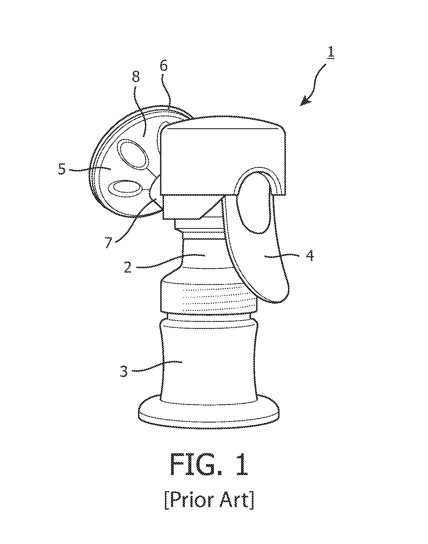
advantage of the present invention is that it is only necessary to create a vacuum in the teat receiving space in order for the resiliently deformable wall 26 to distend. Milk is therefore expressed from the user's breast and is expelled from the funnel 12 through the passageway defined by the first and second shell sections 13,14 of the funnel 12 into the main body of the breast pump 1 and into the milk receiving vessel 3.
[0069]To cause the resiliently deformable wall 26 to distend outwardly into its original position the pressure in the teat receiving space 33 is increased to reduce the pressure differential. Therefore, the resiliently deformable wall 26 is urged to distend outwardly into its original position, away from the teat, due to the resilient nature of the wall 26. As the pressure differential is reduced, the thicker portion 26b of the wall 26 returns to its original shape and position, prior to the thinner portion 26a returning to its original shape and position.
[0070]By cyclically generating a
pressure difference between the pressure chamber 38 and the teat receiving space 33, a repeated peristaltic action is imparted on a user's teat disposed in the insert 23. Therefore, the negative pressure applied in the teat receiving space is less than that required to obtain milk using a conventional breast pump due to the application of the peristaltic movement. Furthermore, when the wall 26 deforms inwardly, the section of the nipple and
areola exposed to the negative air pressure in the teat receiving space 33 is reduced and so the
vacuum level perception is reduced.
[0071]The insert 23 is removable from the second shell section 14 when said second shell section is removed from the first shell section 13 due to the deformable nature of the insert 23, wherein the upper and lower parts 24,25 of the insert 23 can be manipulated to disengage them from the second shell section rims, although other arrangements for removably mounting the insert 23 to the outer shell of the funnel 12 are envisaged. An
advantage of the insert 23 being removable from the funnel 12 is that the insert is easy to clean. Furthermore, due to the limited number of components of the insert, the insert and breast pump
assembly is easy to assemble and simple to manufacture.
[0072]A second exemplary embodiment of the invention will now be described with reference to FIGS. 9 and 10. In this embodiment, the insert and the breast pump configured to receive the insert are generally the same as for the first embodiment, and so a detailed description is omitted herein. Elements of the insert and breast pump which are generally the same as for the first exemplary embodiment retain the same reference numerals, and the insert is used with a breast pump as shown in FIG. 3. However, in this embodiment the shape of the resiliently deformable wall in cross-section is varied.
[0073]Referring now to FIGS. 9 and 10, an insert 40 adapted to fit on the breast-receiving funnel 12 of the breast pump 1 is shown. The insert 40 is removably insertable in the second shell section 14 of the breast receiving funnel 12. An
advantage of this arrangement is that it enables the insert 40 to be removed from the funnel 12 and so the funnel 12 and insert 40 can be easily cleaned and / or sterilized. The insert 40 is formed from a resilient material, such as a suitable rubber,
silicone elastomer or latex material. Alternatively, the insert 40 is formed from a
thermoplastic elastomer.

