Air-fuel ratio control apparatus of a multi-cylinder internal combustion engine

a multi-cylinder, air-fuel technology, applied in the direction of electrical control, process and machine control, instruments, etc., can solve the problems of engine -fuel ratio, engine -fuel ratio, and the leaning value may deviate greatly from the learning value, so as to improve the emission

Active Publication Date: 2012-01-12
TOYOTA JIDOSHA KK
View PDF9 Cites 29 Cited by
  • Summary
  • Abstract
  • Description
  • Claims
  • Application Information

AI Technical Summary

Benefits of technology

[0013]However, in a period in which such an expedited learning control is being performed, when “a state in which the air-fuel ratio of the engine is disturbed / fluctuated transiently / temporarily” occurs, the sub feedback amount changes / varies to a value different from the convergence value temporarily due to the disturbance, and thus, the leaning value may deviate greatly from a value which the learning value is supposed to reach, because the changing speed is increased by the expedited learning control. Consequently, a period in which the air-fuel ratio of the engine deviates from the appropriate value may become longer, and the emission therefore may become worse.

Problems solved by technology

However, in a period in which such an expedited learning control is being performed, when “a state in which the air-fuel ratio of the engine is disturbed / fluctuated transiently / temporarily” occurs, the sub feedback amount changes / varies to a value different from the convergence value temporarily due to the disturbance, and thus, the leaning value may deviate greatly from a value which the learning value is supposed to reach, because the changing speed is increased by the expedited learning control.
Consequently, a period in which the air-fuel ratio of the engine deviates from the appropriate value may become longer, and the emission therefore may become worse.

Method used


Image

  • Air-fuel ratio control apparatus of a multi-cylinder internal combustion engine
  • Air-fuel ratio control apparatus of a multi-cylinder internal combustion engine
  • Air-fuel ratio control apparatus of a multi-cylinder internal combustion engine

Examples


first embodiment

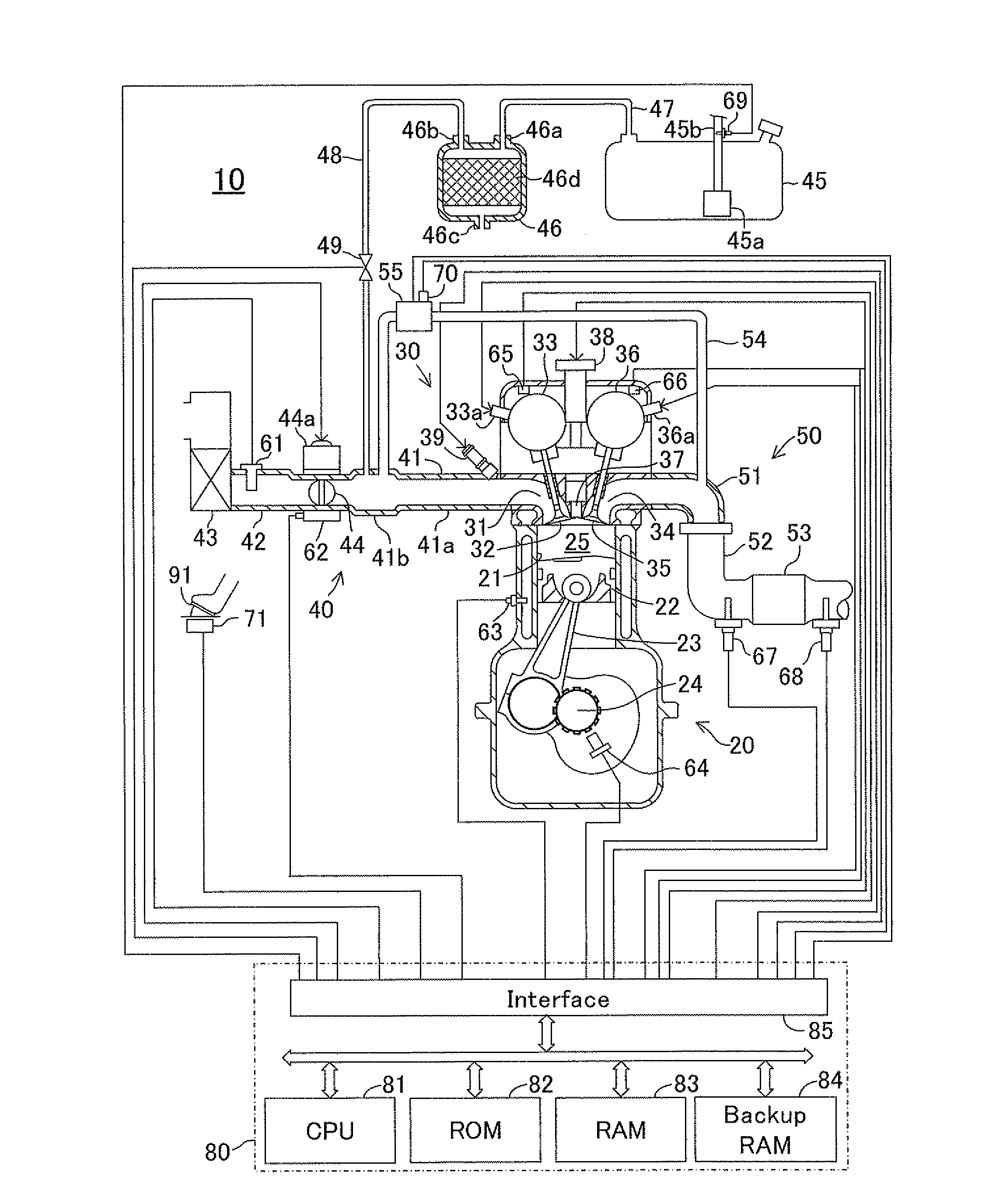
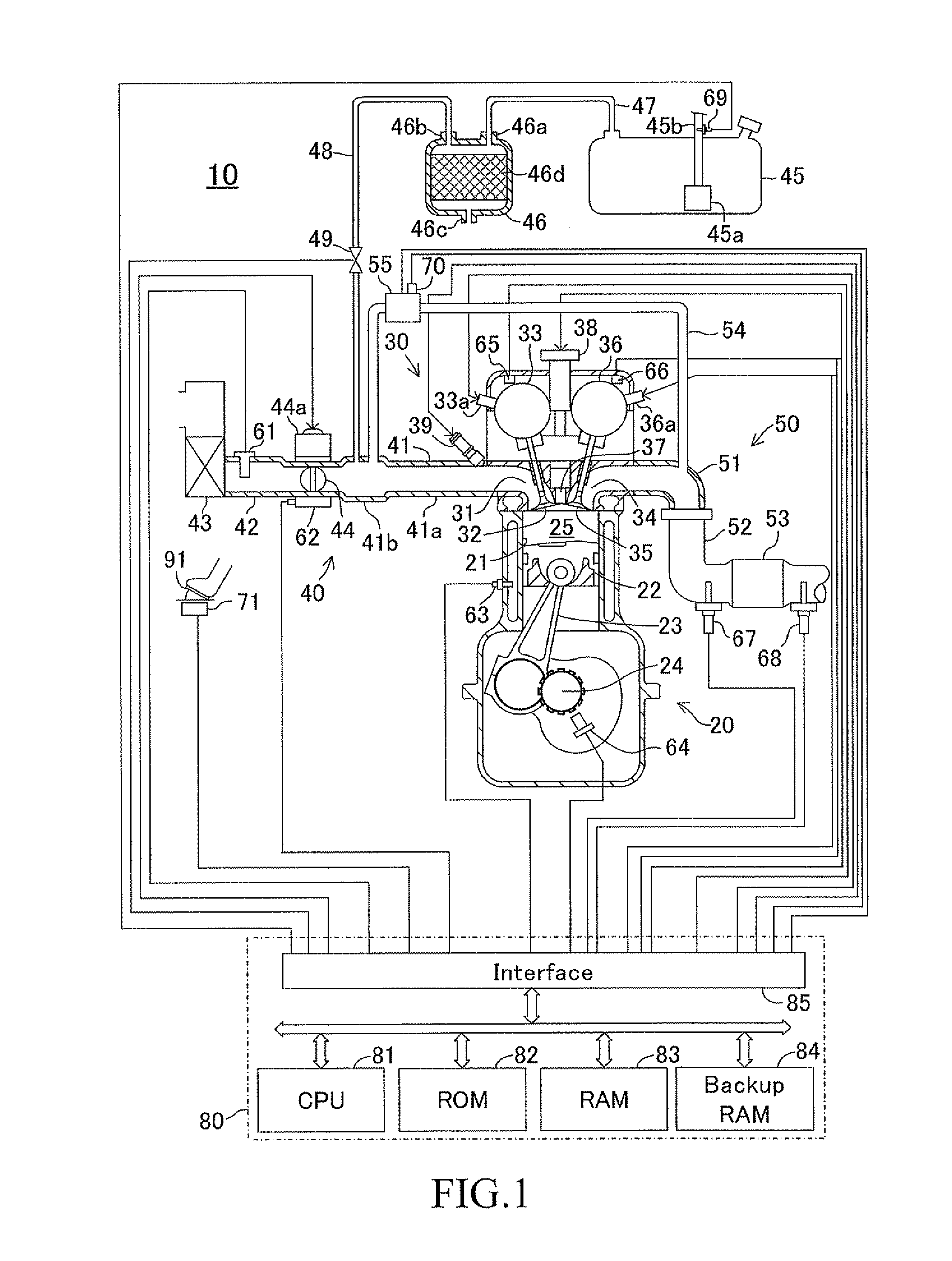
[0157]FIG. 1 shows a schematic configuration of a system in which an air-fuel ratio control apparatus of a multi-cylinder internal combustion engine according to a first embodiment (hereinafter, referred to as a “first control apparatus”) is applied to a 4 cycle, spark-ignition, multi-cylinder (4 cylinder) internal combustion engine 10. FIG. 1 shows a section of a specific cylinder only, but other cylinders also have similar configurations.

[0158]The internal combustion engine 10 includes a cylinder block section 20 including a cylinder block, a cylinder block lower-case, an oil pan, and so on; a cylinder head section 30 fixed on the cylinder block section 20; an intake system 40 for supplying a gasoline mixture to the cylinder block section 20; and an exhaust system 50 for discharging an exhaust gas from the cylinder block section 20 to the exterior of the engine.

[0159]The cylinder block section 20 includes cylinders 21, pistons 22, connecting rods 23, and a crankshaft 24. The pisto...

second embodiment

[0376]An air-fuel ratio control apparatus of a multi-cylinder internal combustion engine according to a second embodiment of the present invention (hereinafter, referred to as a “second control apparatus”) will next be described. The second control apparatus is different from the first control apparatus only in that the condition(s) for setting the air-fuel ratio disturbance occurrence flag XGIRN to “1” or “0” is different from that of the first control apparatus. Accordingly, hereinafter, the difference will mainly be described.

[0377]The CPU 81 of the second control apparatus executes a routine in which steps from step 1035 to step 1050 shown in FIG. 10 are replaced with steps from step 1410 to step 1430 shown in FIG. 14. That is, the CPU 81 proceeds to step 1410 shown in FIG. 14 after it updates the evaporated fuel gas concentration learning value FGPG at step 1030 shown in FIG. 10. At step 1410, the CPU 81 determines whether or not the evaporated fuel gas concentration learning v...

third embodiment

[0384]An air-fuel ratio control apparatus of a multi-cylinder internal combustion engine according to a third embodiment of the present invention (hereinafter, referred to as a “third control apparatus”) will next be described. The third control apparatus is different from the first control apparatus only in that the condition(s) for setting the air-fuel ratio disturbance occurrence flag XGIRN to “1” or “0” is different from that of the first control apparatus. Accordingly, hereinafter, the difference will mainly be described.

[0385]The CPU 81 of the third control apparatus executes a routine in which steps from step 1035 to step 1050 shown in FIG. 10 are replaced with steps from step 1510 to step 1530 shown in FIG. 15. That is, the CPU 81 proceeds to step 1510 shown in FIG. 15 after it updates the evaporated fuel gas concentration learning value FGPG at step 1030 shown in FIG. 10. At step 1510, the CPU 81 determines whether or not the “updating amount tFG obtained at step 1020 shown...


PUM


Abstract

An air-fuel ratio control apparatus includes a catalytic converter disposed at a position downstream of an exhaust gas aggregated portion; a downstream air-fuel ratio sensor disposed in an exhaust passage at a position downstream of the catalytic converter; first feedback amount updating means for updating a first feedback amount to have an output value of the downstream air-fuel ratio sensor coincide with a target downstream-side air-fuel ratio based on the output value of the downstream air-fuel ratio sensor; and a learning means for updating a leaning value of the first feedback amount in such a manner that the leaning value brings in a steady-state component of the first feedback amount based on the first feedback amount.

Description

TECHNICAL FIELD[0001]The present invention relates to an air-fuel ratio control apparatus of a multi-cylinder internal combustion engine, for controlling an air-fuel ratio of a mixture supplied to the engine, based on an output value of an air-fuel ratio sensor disposed downstream of a catalytic converter (catalyst) provided (interposed) in an exhaust passage of the engine.BACKGROUND ART[0002]Conventionally, one of air-fuel ratio control apparatuses of the type comprises an upstream air-fuel ratio sensor, a catalytic converter, and a downstream air-fuel ratio sensor, disposed in this order from an upstream side to a downstream side in an exhaust passage of an engine, and is configured to perform a feedback control on an air-fuel ratio (hereinafter, simply referred to as “an air-fuel ratio of the engine”) of a mixture supplied to the engine, based on an output value of the upstream air-fuel ratio sensor and an output value of the downstream air-fuel ratio sensor.[0003]More specifical...

Claims


Application Information

Patent Timeline
Patent Type & Authority Applications(United States)
IPC IPC(8): F02D41/00
CPCF02D41/006F02D41/2454F02D41/1454F02D41/1441
Inventor DEMURA, TAKAYUKI
Owner TOYOTA JIDOSHA KK
Why Eureka
Try Eureka