Network for Confined Hazardous or Other Extreme Environments

a hazardous environment and network technology, applied in the field of communication networks, can solve the problems of large underground mines, presenting significant safety challenges, and mining can be extremely dangerous exercises, and achieve the effects of efficient propagate signal, enhanced locating specificity, and longer range propagation

Inactive Publication Date: 2012-01-12
ACTIVE CONTROL TECH
View PDF3 Cites 9 Cited by
  • Summary
  • Abstract
  • Description
  • Claims
  • Application Information

AI Technical Summary

Benefits of technology

[0015]Nodes are self-addressing so that the network can be easily extended by in-house mine electricians as required, since the mine face, where coal is extracted, can advance up to three-hundred feet per day.
[0016]Each node can employ a novel antenna design that accommodates a plurality of radios, presently preferred to be four radios, two of which are dedicated to client communications and two of which are dedicated to backhaul communications. Novel directional antennas to propagate signal efficiently down long corridor spaces to get the most robust ‘line-of-sight’ signal. In other aspects, novel new bi-directional (directional) antennas so that locating specificity can be enhanced. Bi-directional antennas are preferred where it is desired to achieve longer range propagation than can be achieved with long-range directional antennas. The signal strength of bi-direction antennas need not show much differentiation (decay) along the furthest ⅔ of its pattern, in that the signal strength at, for example, one-thousand feet can look substantially the same as at, for example, thirteen hundred feet) bi-directional antennas can permit propagation of overlapping patterns and therefore provide more reference points for our locating software which calculates Relative Signal Strength of a client among multiple nodes effectively and assisting in location determination.

Problems solved by technology

While potentially lucrative, mining can be extremely dangerous exercise.
Large underground mines, in particular, present significant safety challenges due to the risk of cave-ins.
Coal mines present even greater challenges due the friable nature of coal and the constant leaking of explosive methane from the coal.
In general, none of the foregoing systems provide a complete range of desirable and satisfactory safety and operational features for a network in a mining or like environment.

Method used


Image

  • Network for Confined Hazardous or Other Extreme Environments
  • Network for Confined Hazardous or Other Extreme Environments
  • Network for Confined Hazardous or Other Extreme Environments

Examples


Embodiment Construction

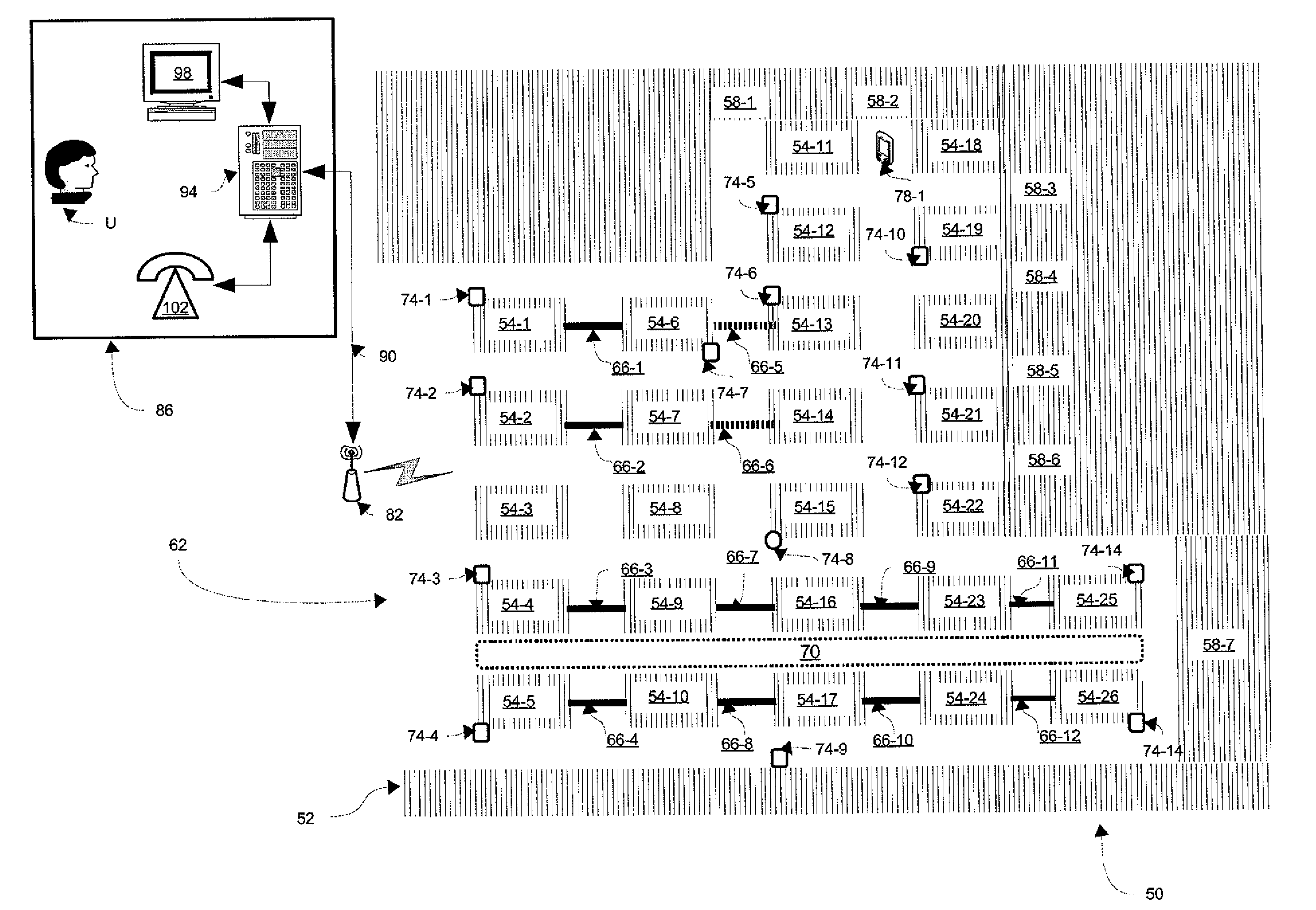
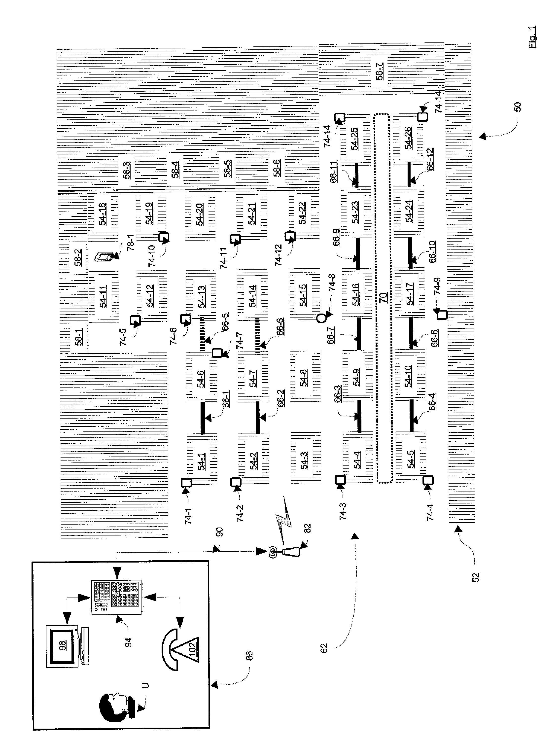
[0029]Referring now to FIG. 1, a room and pillar coal mine is indicated generally at 50. Mine 50 is characterized by a coal seam 52 that has been mined so as to leave a plurality of pillars 54-1, 54-2 . . . 54-26. (Generically, pillar 54, and collectively, pillars 54). The portions of seam 52 that are not pillars 54 but which have yet to be mined are referred to as coal faces and are labeled at 58-1, 58-2, . . . 58-7.

[0030]Mine 50 is also characterized by a plurality of rooms around each pillar 54. Each room (also known as an “entry” of a “cross-cut”) has a width of about twenty feet, and each pillar 54 has a width of about 40-100 feet. Mine 50 can be suitable for long-wall and / or retreat mining whereby each pillar 54 is removed, allowing the roof to collapse, and further adding to the risk of harm for mining personnel.

[0031]Mine 50 is also characterized by an entrance 62 where miners, other personnel and equipment can enter and exit mine 50 and through which coal extracted from min...


PUM


Abstract

A network for a mine or other hazardous environment is provided. The network can include a plurality of access points that can communicate with each other. The access points can be deployed along a plurality of pillars in a room-and-pillar mine. The access points can interconnect a mobile wireless client device within the mine with an operations centre. In the event of an explosion or other disaster, a UPS battery back-up and the redundancy of the access points can increase the likelihood that a link between the wireless client device and the operations center can be maintained.

Description

CROSS-REFERENCE TO RELATED APPLICATIONS[0001]The present application is a continuation of pending U.S. patent application Ser. No. 11 / 649,419 filed Jan. 4, 2007, which claims benefit of U.S. Provisional Patent Application Ser. No. 60 / 826,456, filed Sep. 21, 2006. This application claims the benefit of all of the aforementioned applications and patents. The contents of the above applications are incorporated herein by reference in their entireties.FIELD OF THE INVENTION[0002]The present invention relates generally to communication networks and more specifically to a network for a confined hazardous environment, such as a mine, a granary, an oil or gas refinery, a sawmill, a furniture factory or like environments.BACKGROUND OF THE INVENTION[0003]While potentially lucrative, mining can be extremely dangerous exercise. Large underground mines, in particular, present significant safety challenges due to the risk of cave-ins. Coal mines present even greater challenges due the friable natu...

Claims


Application Information

Patent Timeline
Patent Type & Authority Applications(United States)
IPC IPC(8): H04W4/00H04W16/20
CPCH04W16/20E21F17/18
Inventor BARRETT, STEVESTEIN, ANDY
Owner ACTIVE CONTROL TECH
Why Eureka
Try Eureka