Vacuum Insulation Panel, Insulated Masonry Structure Comprising Same, And Method Of Construction

a technology of vacuum insulation and masonry structure, applied in the field of vacuum insulation panels, can solve the problems of inability to meet the newly mandated insulative properties of the home, the limitation of the amount of thermal resistance possible from the constrained thickness wall, and the traditional insulator, so as to reduce the vacuum level, improve the control of water vapor, and reduce the specific surface area

Inactive Publication Date: 2012-01-12
RUSEK JR STANLEY J
View PDF7 Cites 31 Cited by
  • Summary
  • Abstract
  • Description
  • Claims
  • Application Information

AI Technical Summary

Benefits of technology

The patent describes two versions of an improved design for panels used in building construction. In both versions, there are special layers made of material called VIP which helps keep the panel sealed properly. One version also includes small amounts of active ingredients like absorbers and desiccants which help remove any moisture that might be released over time. Another improvement involves adding a thin layer of insulating foam around the edge of the panel to reduce heat transfer and protection against damage. These improvements make the panels more effective and durable while maintaining their ability to prevent air leakage and provide good thermal performance.

Problems solved by technology

The technical problem addressed in this patent is how to improve the design of vacuum insulation panels (VIPs) for use in buildings. Current VIPs face issues like limited shelf life, vulnerability to damaging environments, and requiring expensive protection enclosures. Additionally, their efficacy rate often decreases quickly over time when installed in masonry wall settings. There is a need for an improvement in the durability and stability of VIPs for construction application in the built environment.

Method used


Image

  • Vacuum Insulation Panel, Insulated Masonry Structure Comprising Same, And Method Of Construction
  • Vacuum Insulation Panel, Insulated Masonry Structure Comprising Same, And Method Of Construction
  • Vacuum Insulation Panel, Insulated Masonry Structure Comprising Same, And Method Of Construction

Examples


Embodiment Construction

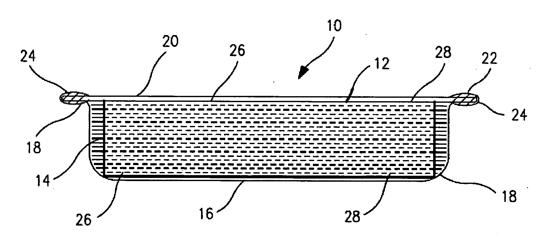
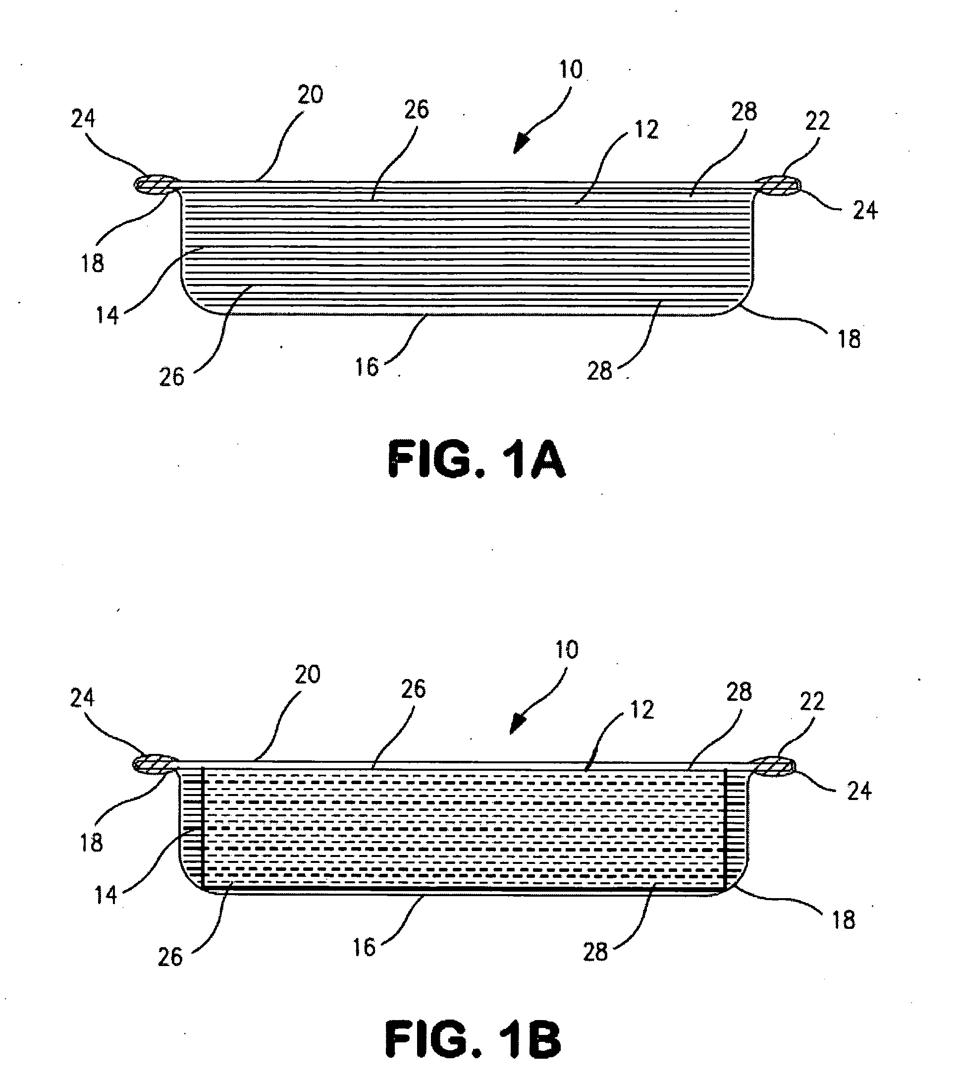
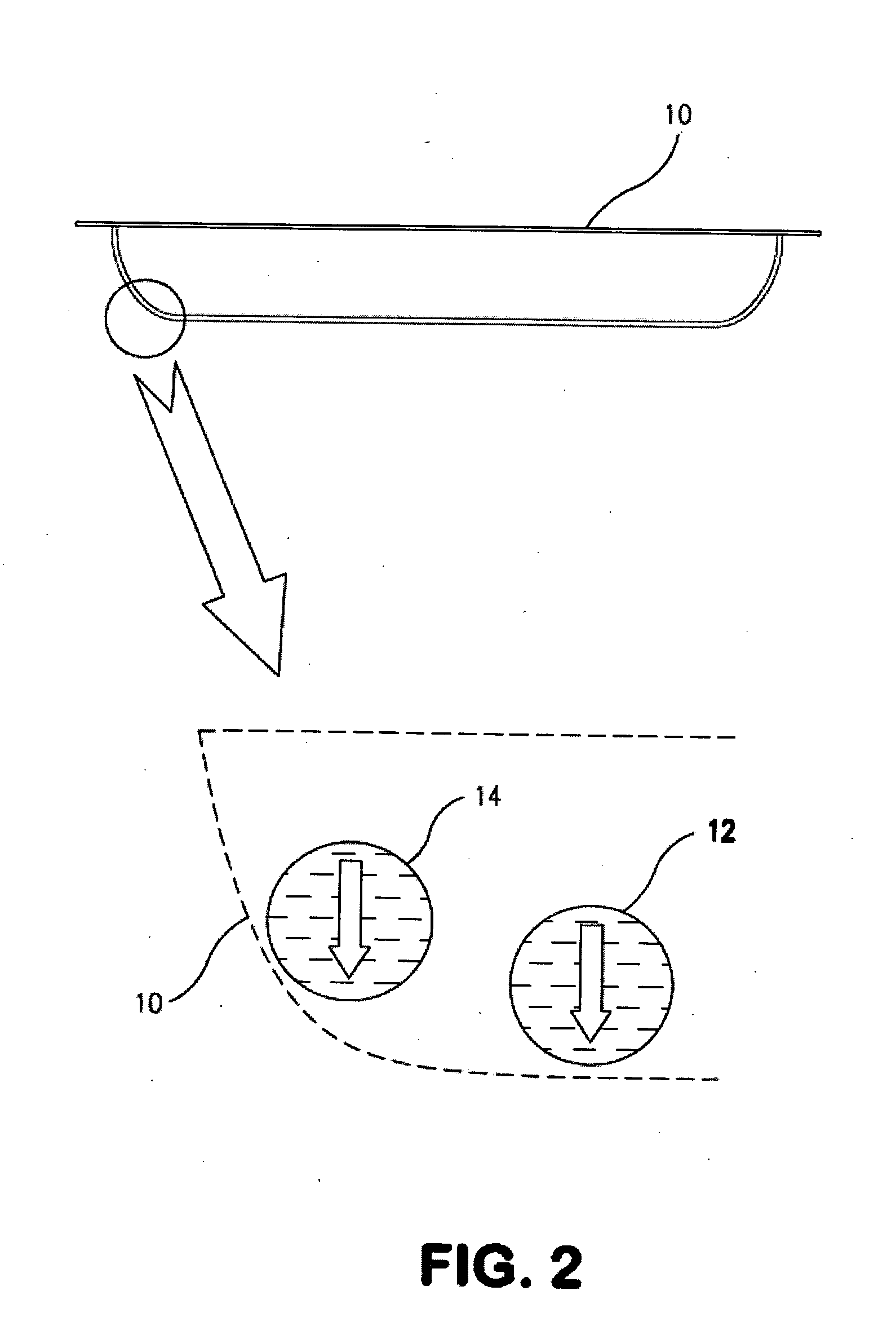
[0069]The present invention is described in terms of a vacuum insulation panel which is particularly suitable for use in the construction industry. This insulation panel can be formed in any shape although for illustration purposes panel 10 is shown rectangular in shape. As illustrated in FIG. 1A, an insulation panel shown generally at 10 produced according to the present invention has a core 12 comprised of multiple stacked layers of non-woven organic free fiberglass sheets or plies 14. In a preferred embodiment, as illustrated in FIG. 1A, vacuum insulation panel 10 is formed from two stainless steel foil sections, viz. a first pan-shaped section 16 having rounded corners 18, and a second pan of equal or shallower depth or a flat section 20 formed from a rolled sheet of the same stainless steel foil as pan section 16. The joint 22 at the edge of enclosure 10 is preferably sealed by resistance seam welding.

[0070]Although conventional stamping can be used to form pan 16, in a preferr...


PUM

PropertyMeasurementUnit
Temperatureaaaaaaaaaa
Lengthaaaaaaaaaa
Lengthaaaaaaaaaa

Abstract

A vacuum insulation panel is provided comprising a core with a plurality of stacked non-woven organic free glass fiber sheets, plies, or net shape one piece glass fiber core and a vacuum sealed enclosure containing the core. The fiberglass sheets are formed from glass fibers having a nominal diameter of about 1.5-3.0 microns and the enclosure is formed from an annealed stainless steel foil. The vacuum insulation panel has a thickness of from about 1 to 2.5 inches and an insulation value R of at least 56.8 at moderate vacuum levels between about 1.0E−02 to 1.0E+01 mTorr. In addition, a method of manufacturing same is provided, as well as a method of construction, wherein the vacuum insulation panel is disposed between two walls in the gap therebetween, and preferably a filler material, such as aerated concrete, fiberglass, foam, etc., is disposed in the gap so as to partially or fully encase the vacuum insulation panel.

Description


Claims


Application Information

Patent Timeline
Owner RUSEK JR STANLEY J
Why Eureka
Try Eureka