
Method for determining the correct natural head position location of references planes relative to a three-dimensional computerized image of a patient's head

a three-dimensional computerized image and reference plane technology, applied in the field of facial measurement and analysis, can solve the problems of poor profile, unbalanced overall face, difficult to quantify, etc., and achieve the effect of excellent results

Inactive Publication Date: 2012-01-12
ARNETT FACIAL RECONSTR COURSES
View PDF2 Cites 23 Cited by
  • Summary
  • Abstract
  • Description
  • Claims
  • Application Information

AI Technical Summary

Benefits of technology

[0013]One object of the invention is to provide a method to correlate a profile view of a patient's face in the natural head position with a 3D computerized view of the patient head and face to aid in an analysis that focuses on soft tissue landmarks as opposed primarily to hard tissue to achieve consistently excellent outcomes in dental, orthodontic and surgical correction of facial imbalance in frontal view and in frontal plus profile view so that the face and head may be studied in 3D from a variety of angles.

Problems solved by technology

Facial attractiveness, while innately recognizable by lay people and artists, has in the past been difficult to quantify.
While a good profile is an essential part of good facial aesthetics, it is possible to have a good profile yet still have an overall unbalanced face if the front view has imperfections.
However when the patient's head is locked in place with the forehead strap and chin cup in preparation for the CBCT scan, the patient's head is rarely in the natural head position and is facing up or down, rotated on the neck, and / or tilted side to side, with the result that when the scan is taken, the head is not a natural head position.
Therefore, the three-dimensional computerized image of the patient's face and head thus scanned will not be correlated to either the patient's “natural head position” and the positions of the coronal, transverse, or sagittal planes will not be knowable to the practitioner viewing and needing to work with the 3D computerized image of the patient's head and face.
Thus, the practitioner who is using the specialized imaging software will be at a great disadvantage when using the CBCT scanned 3D image of the patient's head and face in treatment planning and execution.

Method used


Image

  • Method for determining the correct natural head position location of references planes relative to a three-dimensional computerized image of a patient's head
  • Method for determining the correct natural head position location of references planes relative to a three-dimensional computerized image of a patient's head
  • Method for determining the correct natural head position location of references planes relative to a three-dimensional computerized image of a patient's head

Examples


Embodiment Construction

[0025]In the invention, the frontal head posture and measurements will be used in conjunction with the profile postural head position and measurements in order to create a 3-D model of the face and head.

[0026]A frontal and profile head position images will be taken with conventional CT scans, cone beam computed tomography (CBCT), 3D photography, 2D photography, scattered light photography, laser scanning, profile and frontal cephalometrics, ultrasound and magnetic resonance imaging, or any other imaging technique that presently exists or in the future may be developed.

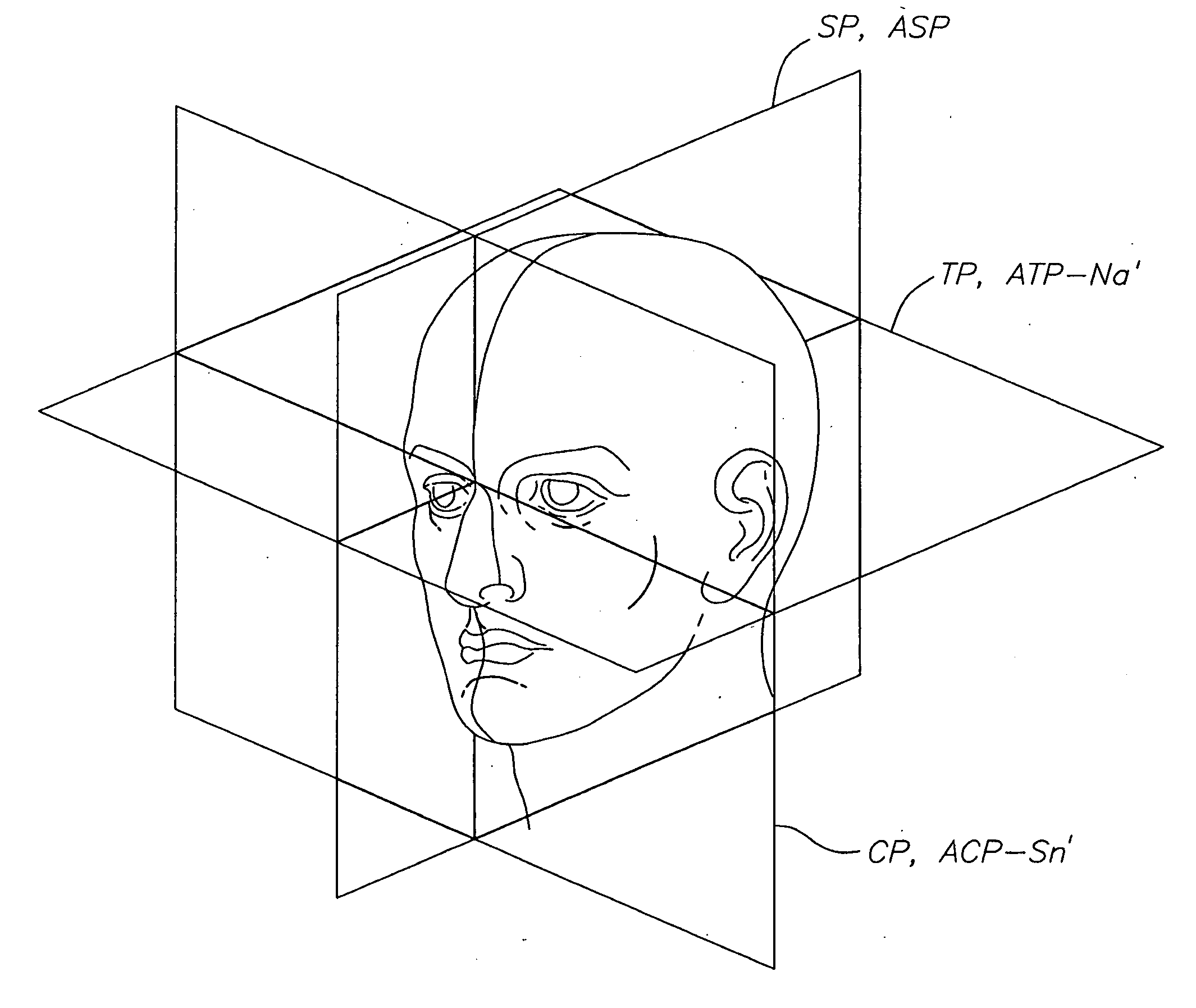
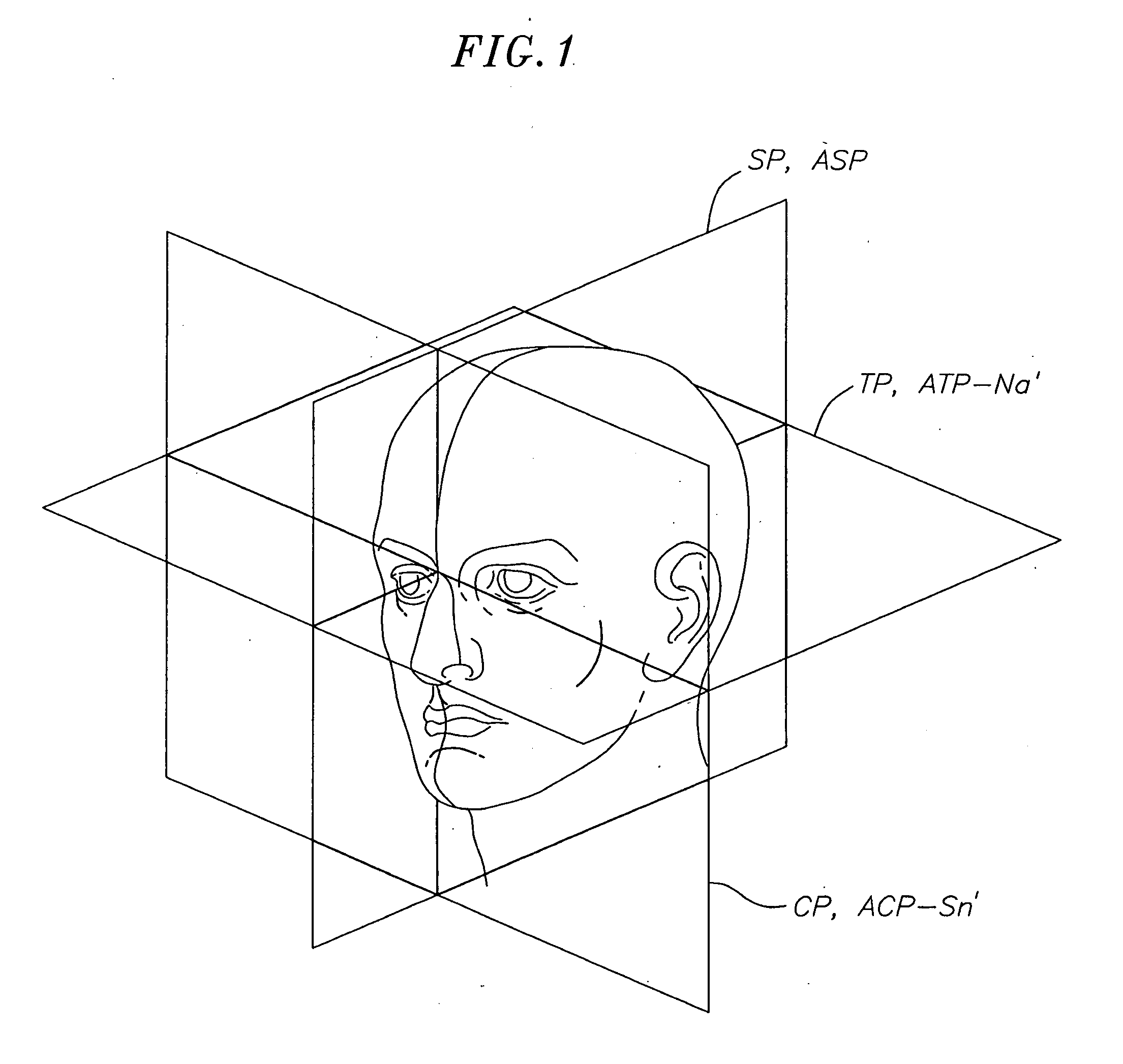
[0027]In order to position the head in the proper anatomical position, it is necessary to properly orient the head with respect to three perpendicular anatomical reference planes, namely the sagittal plane SP, the transverse plane TP, and coronal plane CP. These three anatomical planes of references are shown in FIG. 1 with reference to a diagrammatic head and face.

[0028]The sagittal plane SP is perpendicular to the fl...


PUM


Abstract

A system and method for determining the correct natural head position location of reference planes, i.e., the coronal, transverse, and sagittal planes, relative to a three-dimensional computerized image of a patient's head. This method will allow medical practitioners to accurately measure various soft tissue features of the patient's face and underlying hard tissue structures, e.g., such as dentoskeletal structures, and combining such analysis with profile analysis and treatment planning for full 3D facial analysis.

Description

CROSS REFERENCE TO RELATED APPLICATIONS[0001]The application is a continuation-in-part of U.S. patent application Ser. No. 11 / 252,411, filed Oct. 17, 2005, which claims the benefit of and the priority to 61 / 432,127 filed Jan. 12, 2011 and the entire contents of which are incorporated by reference herein.FIELD OF THE INVENTION[0002]The invention relates generally to the field of facial measurement and analysis, and more particularly to a system and method for determining the correct natural head position location of reference planes, i.e., the coronal, transverse, and sagittal planes, relative to a three-dimensional computerized image of a patient's head. This method will allow medical practitioners to accurately measure various soft tissue features of the patient's face and underlying hard tissue structures, e.g., such as dentoskeletal structures, and combining such analysis with profile analysis and treatment planning for full 3D facial analysis.BACKGROUND[0003]The study of facial ...

Claims


Application Information

Patent Timeline
Patent Type & Authority Applications(United States)
IPC IPC(8): A61B5/103
CPCA61B5/0064A61B5/6814A61B5/1077A61B5/1075G06V20/64G06V40/171
Inventor ARNETT, G. WILLIAMGUNSON, MICHAEL J.
Owner ARNETT FACIAL RECONSTR COURSES
Learn More