

Drive assembly suitable for use in a drug delivery device and drug delivery device
- Summary
- Abstract
- Description
- Claims
- Application Information
AI Technical Summary
Benefits of technology
Problems solved by technology
Method used
Image

Examples
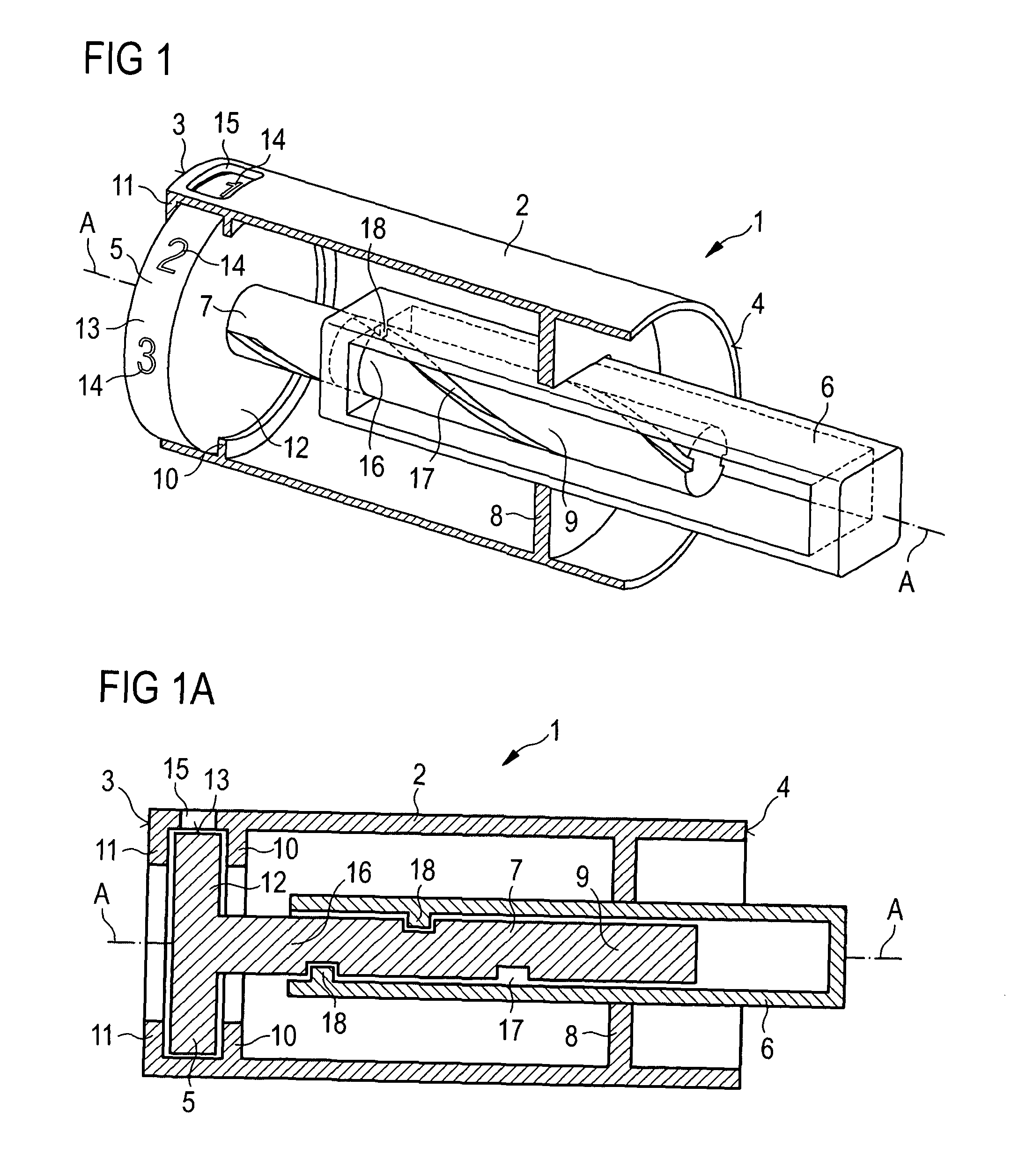
first embodiment
[0170]As compared to the first embodiment, one region or a plurality of regions of the (helical) thread formed on rotation member 7 can be replaced by a region that runs parallel to axis A, with the indicator not rotating while the rotation member is coupled to the piston rod in the region that runs parallel to axis A.
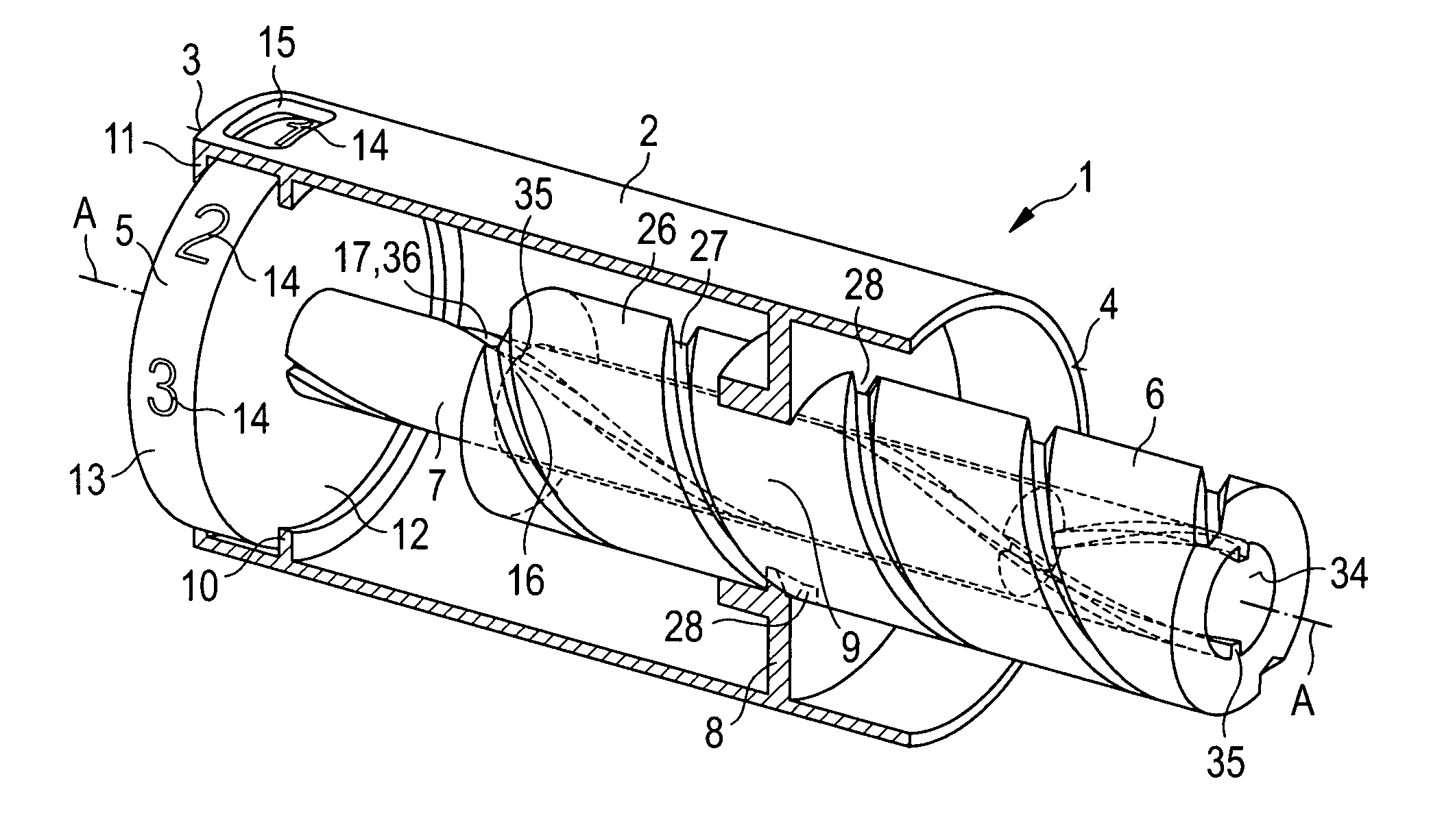
[0171]FIG. 3 shows an oblique sectional view of a third embodiment of the drive assembly 1. The third embodiment essentially corresponds to the embodiment described in conjunction with FIGS. 1 and 1A.
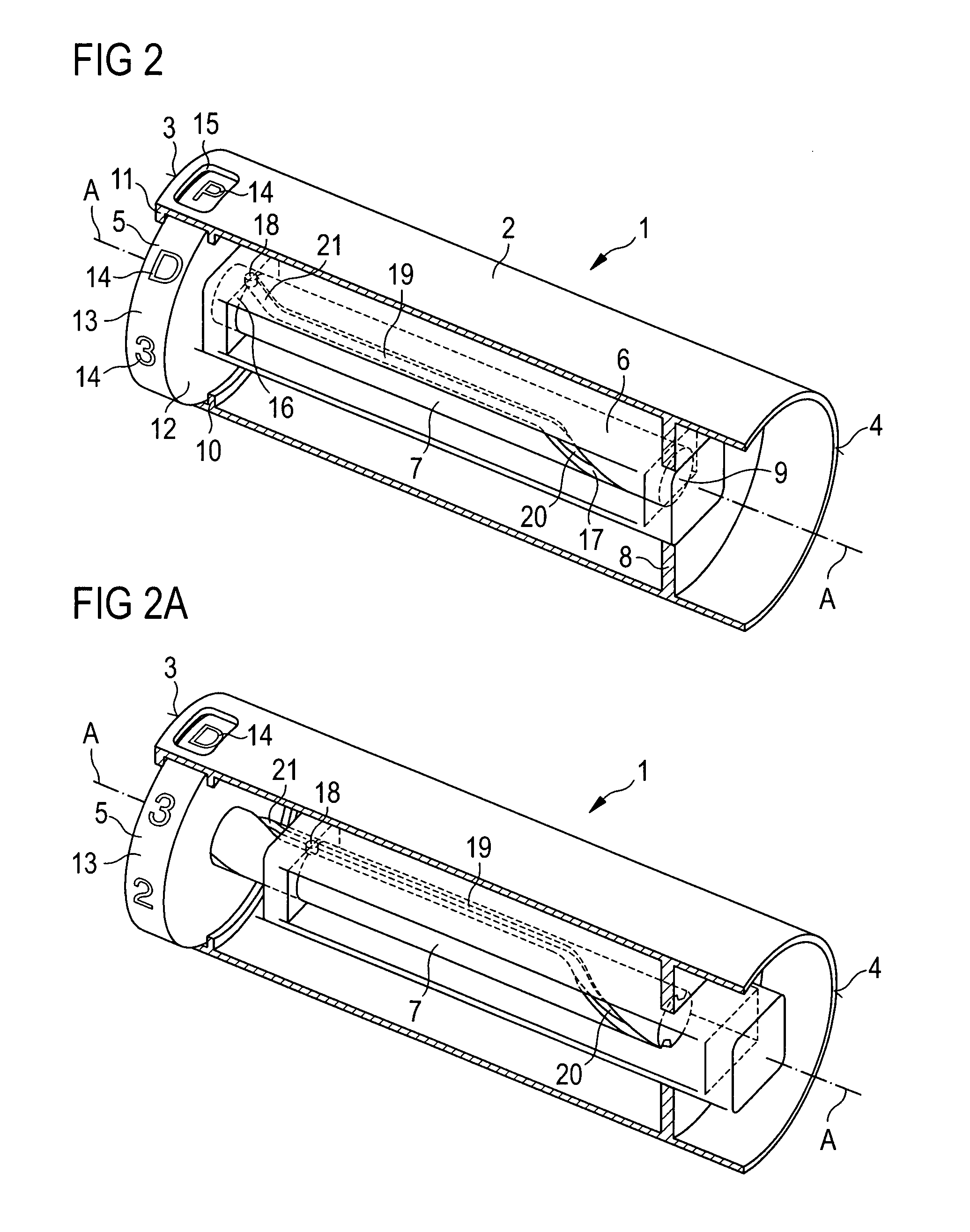
third embodiment
[0172]In contrast thereto, the drive assembly 1 comprises a plurality of indication surfaces, which are arranged side by side along the axis A. For example, indicator 5 comprises two indication surfaces 13 and 22. Each of those indication surfaces can be provided with a plurality of index elements 14. Indication surfaces 13 and 22 may be non-rotatable relative to one another.
[0173]In this embodiment, the indicator 5, in particular indicator part 12 thereof, which comprises indication surfaces 13 and 22, is threadedly coupled to the housing 2. Preferably, indicator 5 is threadedly engaged to the housing 2. Housing 2 can comprise a (helical) thread 23 that engages a (helical) thread 24 of indicator part 12.
[0174]If the indicator 5 rotates, the indication surface 22 can be rotated into indication position and replace indication surface 13 in this position. That is to say, indication surface 13 can be rotated away from the window and indication surface 22 can be moved under the window,...
fourth embodiment
[0180]FIG. 4 shows an oblique sectional view of the drive assembly 1. The drive assembly shown in FIG. 4 essentially corresponded to the one described in conjunction with FIG. 3.
[0181]In contrast thereto, indicator 5 comprises two indicator parts 12 and 25 which can be rotated with respect to one another. Indicator part 12 can comprise indication surface 13. Indicator part 25 can comprise indication surface 22. Both indication surfaces 13 and 22 are visible from the outside through window 15.
[0182]Indication surfaces 22 and 13 are rotatable relative to one another. Indicator parts 12 and 25 may be coupled to one another via an odometer(-like) mechanism. A rotation by a predetermined angle, for example a full rotation about 360°, of indicator part 12 relative to indicator part 25 may cause indicator part 25 to rotate, preferably about an angle smaller than the predetermined angle, such that the next index element 14 of indication surface 22 is rotated into indication position.
[0183]I...
PUM
 Abstract
Description
Claims
Application Information