
Reservoir Quality Characterization Using Heterogeneity Equations With Spatially-Varying Parameters

a technology of heterogeneity equations and spatial variables, applied in the field of geologic modeling, can solve the problems of inability to capture information at scales smaller, cell negatively affecting computer processing times, memory usage and storage space requirements, and models that are too large become impractical for us

Inactive Publication Date: 2012-01-12
BENSON GREGORY S
View PDF11 Cites 44 Cited by
  • Summary
  • Abstract
  • Description
  • Claims
  • Application Information

AI Technical Summary

Benefits of technology

"The patent text describes methods for approximating the measurement-based values of geological attributes in a subsurface formation using linear or non-linear expressions. The expressions are determined based on an objective function that is to be minimized. The values of the expressions are outputted and mapped to represent the geological attribute at all locations in the subsurface formation. The methods can be used to predict the flow of hydrocarbons within the formation. The technical effects of the patent text include improved accuracy in predicting the geological attributes of a subsurface formation and improved efficiency in extracting hydrocarbons from the formation."

Problems solved by technology

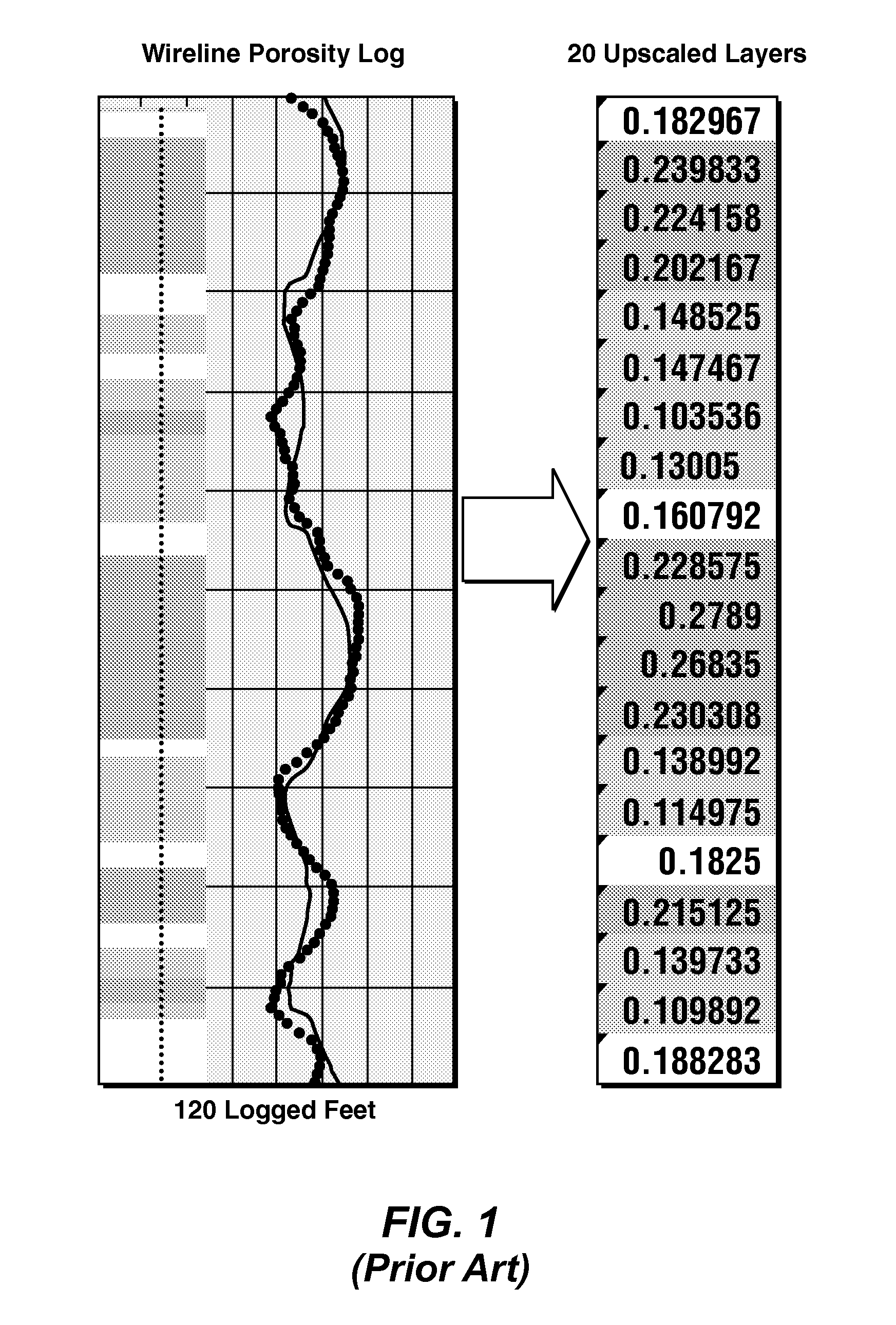
One problem with known geologic modeling tools is that they do not capture information at scales smaller than the sizes of the physical dimensions of their finest spatial elements—the model cells.
Consequently, the number of cells required to describe in detail a medium-sized field can be on the order of tens of millions of cells, and such large numbers of cells negatively impact computer processing times, memory usage, and storage space requirements.
Models that are too large become impractical for use.
The choice of the geologic model cell size is a difficult compromise, and sometimes it is only after a geologic model is completed that it is discovered that an initial choice of model cell size was not optimum.
Unfortunately, because the production history (or future prediction) may span many years, these simulation models require a great many time steps.
This poses a problem because the large number of time steps combined with the large number of equations to be solved at each time step can cause flow simulations to run very slowly, if at all.
The reliability of the algorithms is compromised when the amount of fluid entering and leaving a cell during a time step is too close to the total fluid storage capability of the cell.
These discrepancies may be in observed fluid production rates, reservoir pressures, gas-oil ratios, and pressure-supporting injectant breakthrough times. When outputs of a reservoir simulator are not consistent with the known past history of a field, the simulator cannot be trusted to predict field behavior into the future.
Other times, analysis of these discrepancies reveals that the simulation model cells were not designed small enough to capture the detail necessary to duplicate known historic reservoir performance.
However, if analysis reveals that the simulation cells should be made smaller than the source geologic model cells, the situation will be more difficult to remedy.
Rebuilding a geologic model to add more detail is a costly undertaking, possibly taking as long as the building of the original inadequate model, and often resulting in something so large and unwieldy that it cannot be used.
The sheer number of geomodel cells required to capture this finer detail can itself become a problem by slowing down computer processing, consuming large volumes of computer disk space, and requiring impractical lengths of time to execute the construction processes.
Worse, when geologic model cell counts rise above a certain threshold, the data volume will overwhelm the memory capacity of the computer on which the simulation is running, and the process of upscaling the source geologic model into simulation scale cells can fail.

Method used

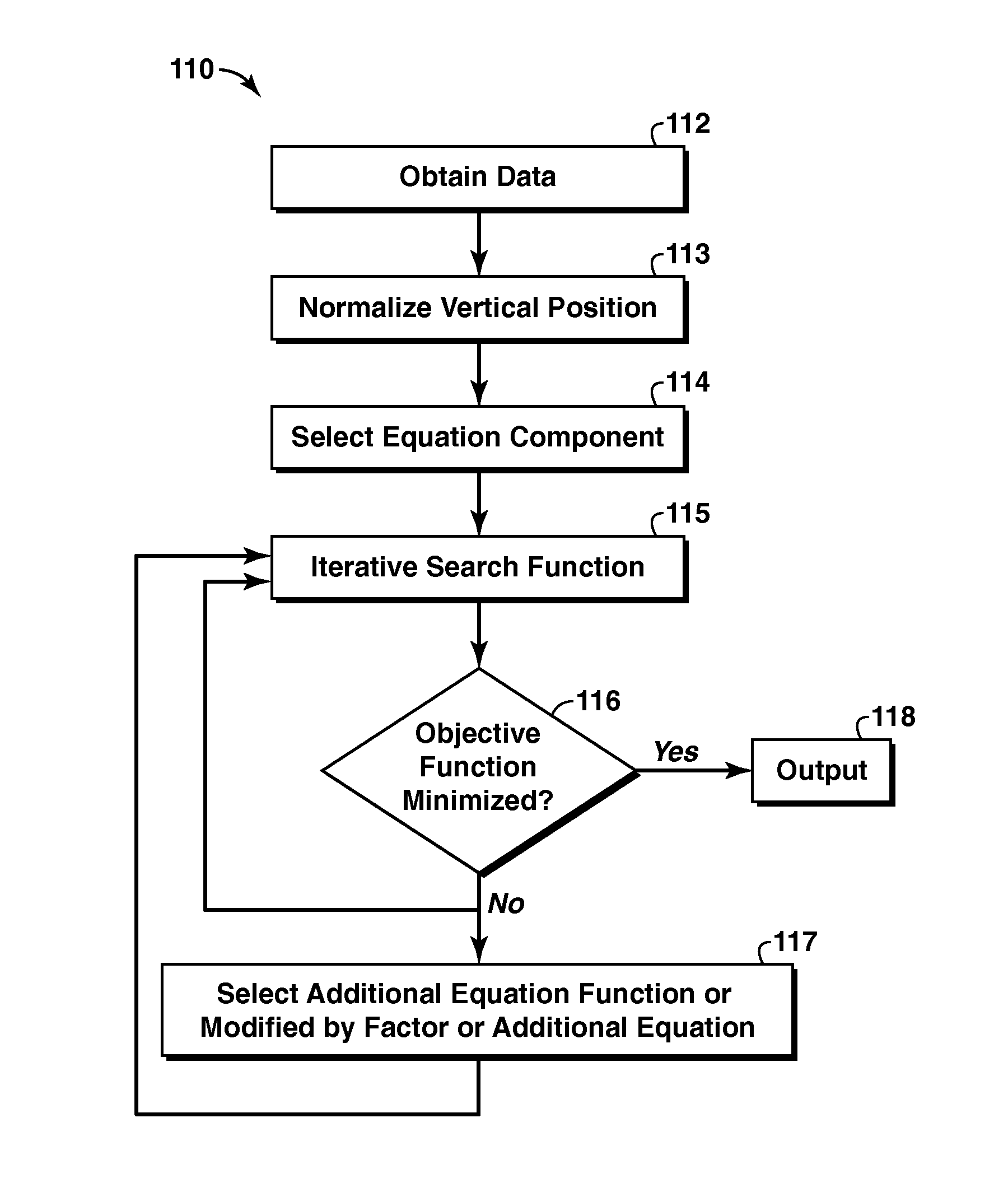

Image

  • Reservoir Quality Characterization Using Heterogeneity Equations With Spatially-Varying Parameters
  • Reservoir Quality Characterization Using Heterogeneity Equations With Spatially-Varying Parameters
  • Reservoir Quality Characterization Using Heterogeneity Equations With Spatially-Varying Parameters

Examples


Embodiment Construction

[0052]Specific embodiments are described in the following detailed description section. To the extent the following description is specific to a particular embodiment or a particular use, this is intended to be for example purposes only and simply provides a description of the embodiments provided herein as representative examples of the invention. Accordingly, the disclosed aspects are not limited to the specific embodiments described below, but rather include all alternatives, modifications, and equivalents falling within the spirit and scope of the appended claims.

[0053]Some portions of the detailed description which follows are presented in terms of procedures, steps, logic blocks, processing and other symbolic representations of operations on data bits within a computer memory. These descriptions and representations are the means used by those skilled in the data processing arts to most effectively convey the substance of their work to others skilled in the art. In this detaile...


PUM


Abstract

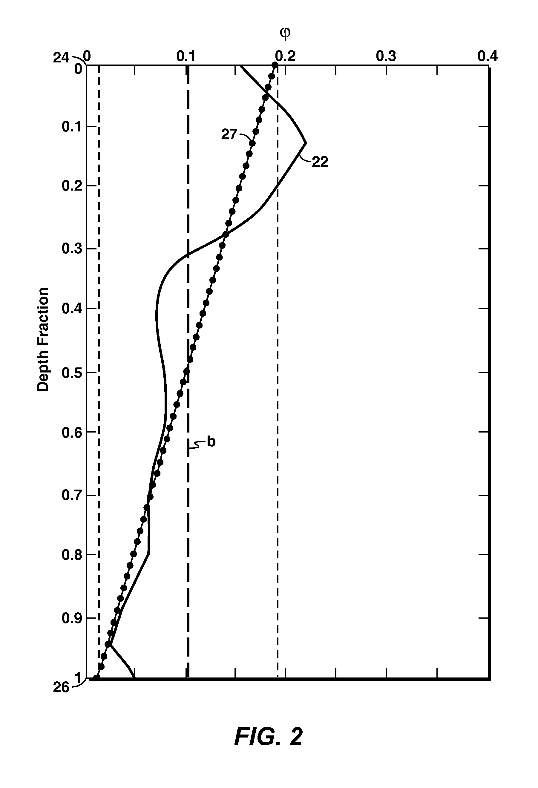
A method is disclosed wherein an expression is selected to approximate measurement-based values of a geologic attribute along a dimension of a subsurface formation as a function of position along the dimension. Values for terms of the expression are determined such that the expression satisfies an objective function to within a predetermined amount. The objective function indicates a difference between outputs of the expression and the measurement-based values at similar points along the dimension. The expression and the values of the terms of the expression are outputted, which includes mapping the terms of the expression to represent the geologic attribute in the subsurface formation such that the geologic attribute is described at all locations in the subsurface formation using the expression and the values of the terms of the expression.

Description

CROSS-REFERENCE TO RELATED APPLICATION[0001]This application claims the benefit of U.S. Provisional Patent Application 61 / 164,224 filed 27 Mar. 2009 entitled RESERVOIR QUALITY CHARACTERIZATION USING HETEROGENEITY EQUATIONS WITH SPATIALLY-VARYING PARAMETERS, the entirety of which is incorporated by reference herein.TECHNICAL FIELD[0002]Disclosed aspects relate generally to geologic modeling, and more specifically, to computer-based systems and methods that allow formation of a geologic model of a subsurface region of interest, such as a sedimentary basin or a petroleum reservoir.BACKGROUND OF THE DISCLOSURE[0003]This section is intended to introduce various aspects of the art, which may be associated with embodiments of the invention. A list of references is provided at the end of this section and may be referred to hereinafter. This discussion, including the references, is believed to assist in providing a framework to facilitate a better understanding of particular aspects of the i...

Claims


Application Information

Patent Timeline
Patent Type & Authority Applications(United States)
IPC IPC(8): G06G7/48
CPCG01V11/00
Inventor BENSON, GREGORY S.
Owner BENSON GREGORY S
Learn More