
Integrated lens antennas for multi-pixel receivers for planetary and astronomical instruments

a multi-pixel receiver and integrated lens technology, applied in the field of antennas and detectors, can solve the problems of limiting the size of such an array, difficult and expensive design, and high cost of feedhorn approaches

Inactive Publication Date: 2012-01-19
CALIFORNIA INST OF TECH
View PDF5 Cites 8 Cited by
  • Summary
  • Abstract
  • Description
  • Claims
  • Application Information

AI Technical Summary

Benefits of technology

The present invention is about integrating lens antennas with receivers. The invention provides methods and apparatus for fabricating a lens with a dielectric material and flowing it into a desired shape. The lens antenna has a dielectric material, a waveguide feed, and a lens. The invention allows for the efficient coupling of lens antennas with receivers. The technical effect of the invention is to improve the performance of lens antennas and receivers.

Problems solved by technology

Feedhorns for such focal planes typically have excellent performance, but the mass, size, and fabrication challenges for such feedhorns, as well as the costs for such devices, typically make a feedhorn approach cost prohibitive for very large focal planes.
However, most planar antenna designs produce broad beam patterns, and therefore require additional elements for efficient coupling to the telescope optics, such as substrate lenses or micro-machined horns.
This does not necessarily preclude their use in large arrays, and indeed large arrays using substrate lenses are being investigated; however, the issues of manufacture and assembly of a large “fly's eye” array of lenses makes such designs difficult and expensive.
While it is also possible to place an array of antennas behind a single lens, optical aberrations limit the size of such an array.

Method used


Image

  • Integrated lens antennas for multi-pixel receivers for planetary and astronomical instruments
  • Integrated lens antennas for multi-pixel receivers for planetary and astronomical instruments
  • Integrated lens antennas for multi-pixel receivers for planetary and astronomical instruments

Examples


Embodiment Construction

[0020]In the following description of the preferred embodiment, reference is made to the accompanying drawings, which form a part hereof, and in which is shown by way of illustration a specific embodiment in which the invention may be practiced. It is to be understood that other embodiments may be utilized and structural changes may be made without departing from the scope of the present invention.

[0021]Overview

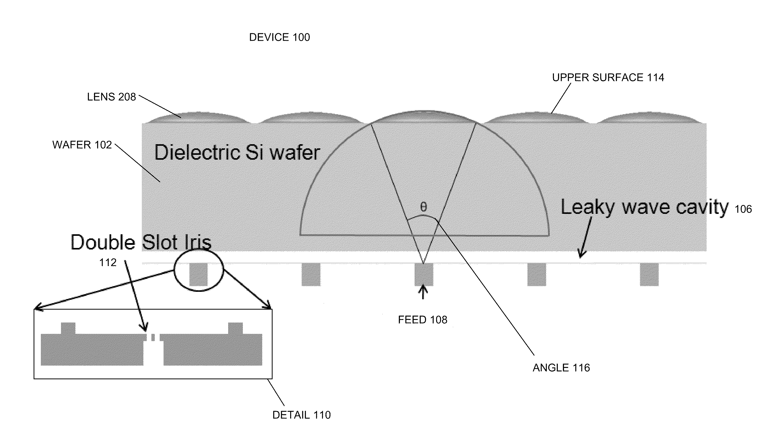
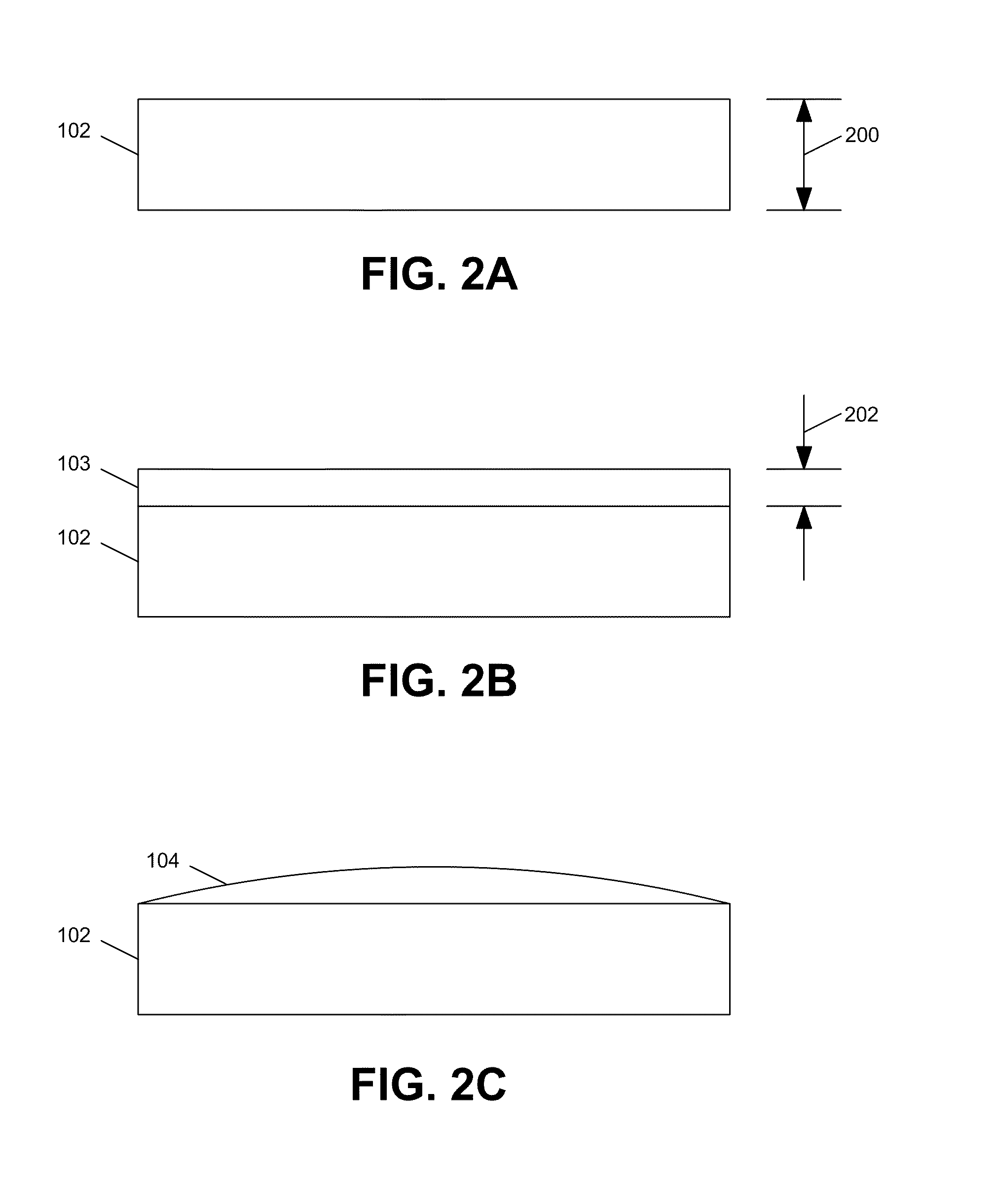
[0022]The present invention discusses integrated silicon micro lenses which can be fabricated photolithographically. These lenses can be fabricated as a single lens or as an array of lenses. The present invention's approach eliminates manual assembly of lens arrays and also reduces assembly errors and tolerances. Moreover, an antenna array without metallic horns as described with respect to the present invention reduces the mass of any planetary instrument significantly.

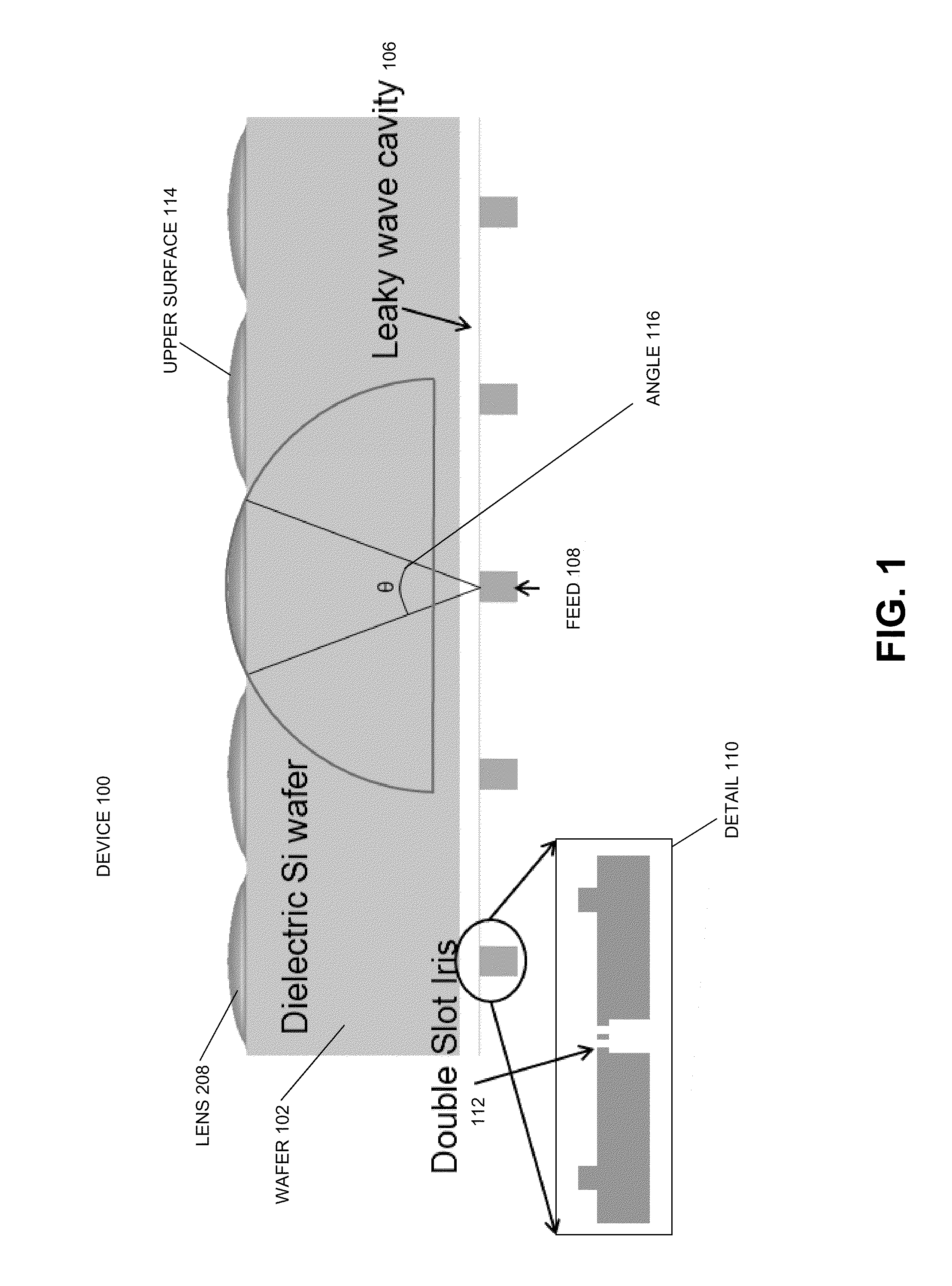
[0023]FIG. 1 illustrates a side view of a lens array in accordance with one or more embodiments of the pres...


PUM

PropertyMeasurementUnit
angleaaaaaaaaaa
shapeaaaaaaaaaa
dielectricaaaaaaaaaa

Abstract

Methods and apparatus for integrating lens antennas for receivers are disclosed. A method of fabricating a lens in accordance with one or more embodiments of the present invention comprises integrating lens material with a dielectric material and flowing the lens material into a desired lens shape. An integrated lens antenna in accordance with one or more embodiments of the present invention comprises a dielectric material, a waveguide feed, coupled to the dielectric material through a leaky wave cavity, and a lens, coupled to the dielectric material opposite the leaky wave cavity, wherein material is first deposited onto the dielectric material, flowed into a desired lens shape and the desired lens shape is transferred to the dielectric material.

Description

CROSS REFERENCE TO RELATED APPLICATIONS[0001]This application claims the benefit under 35 U.S.C. Section 119(e) of the following co-pending and commonly-assigned U.S. provisional patent application(s), which is / are incorporated by reference herein:[0002]Provisional Application Ser. No. 61 / 354,579, filed on Jun. 14, 2010, by Choonsup Lee, Goutam Chattopadhyay, and Nuria Llombart Juan, entitled “INTEGRATED LENS ANTENNAS FOR MULTI-PIXEL RECEIVERS FOR PLANETARY AND ASTRONOMICAL INSTRUMENTS,” attorneys' docket number CIT-5380-P2,[0003]which application is incorporated by reference herein.BACKGROUND OF THE INVENTION[0004]1. Field of the Invention[0005]This invention relates to antennas and detectors used in astrophysics and planetary experiments, and methods for creating antenna lens arrays for use in spectroscopy and other applications.[0006]2. Description of the Related Art[0007]Space exploration and astrophysical studies have been undertaken by several countries for several decades. Cu...

Claims


Application Information

Patent Timeline
Patent Type & Authority Applications(United States)
IPC IPC(8): H01Q15/08H01P11/00
CPCH01Q13/22Y10T29/49016H01Q15/08
Inventor LEE, CHOONSUPCHATTOPADHYAY, GOUTAMLLOMBART, NURIA
Owner CALIFORNIA INST OF TECH
Learn More