

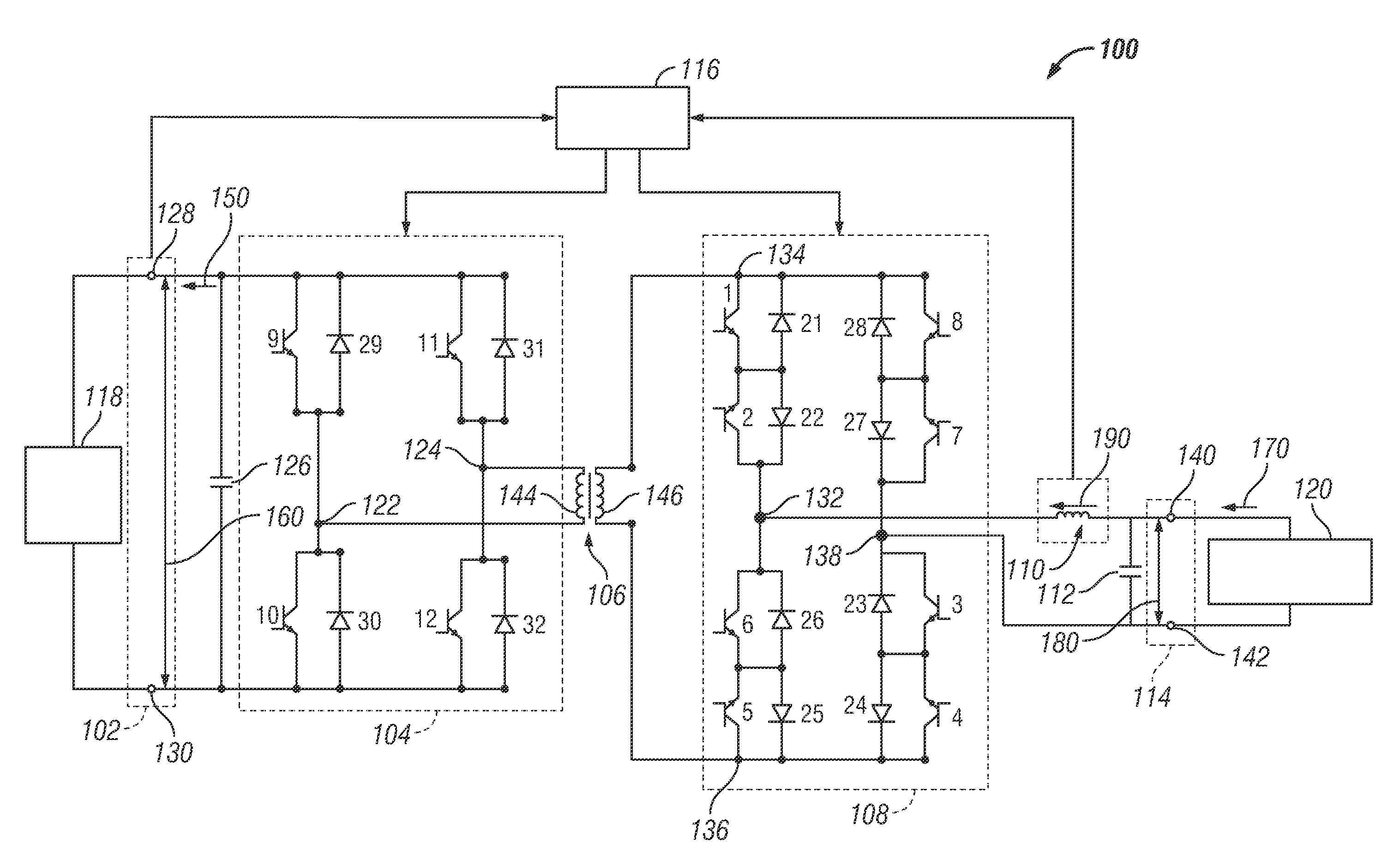
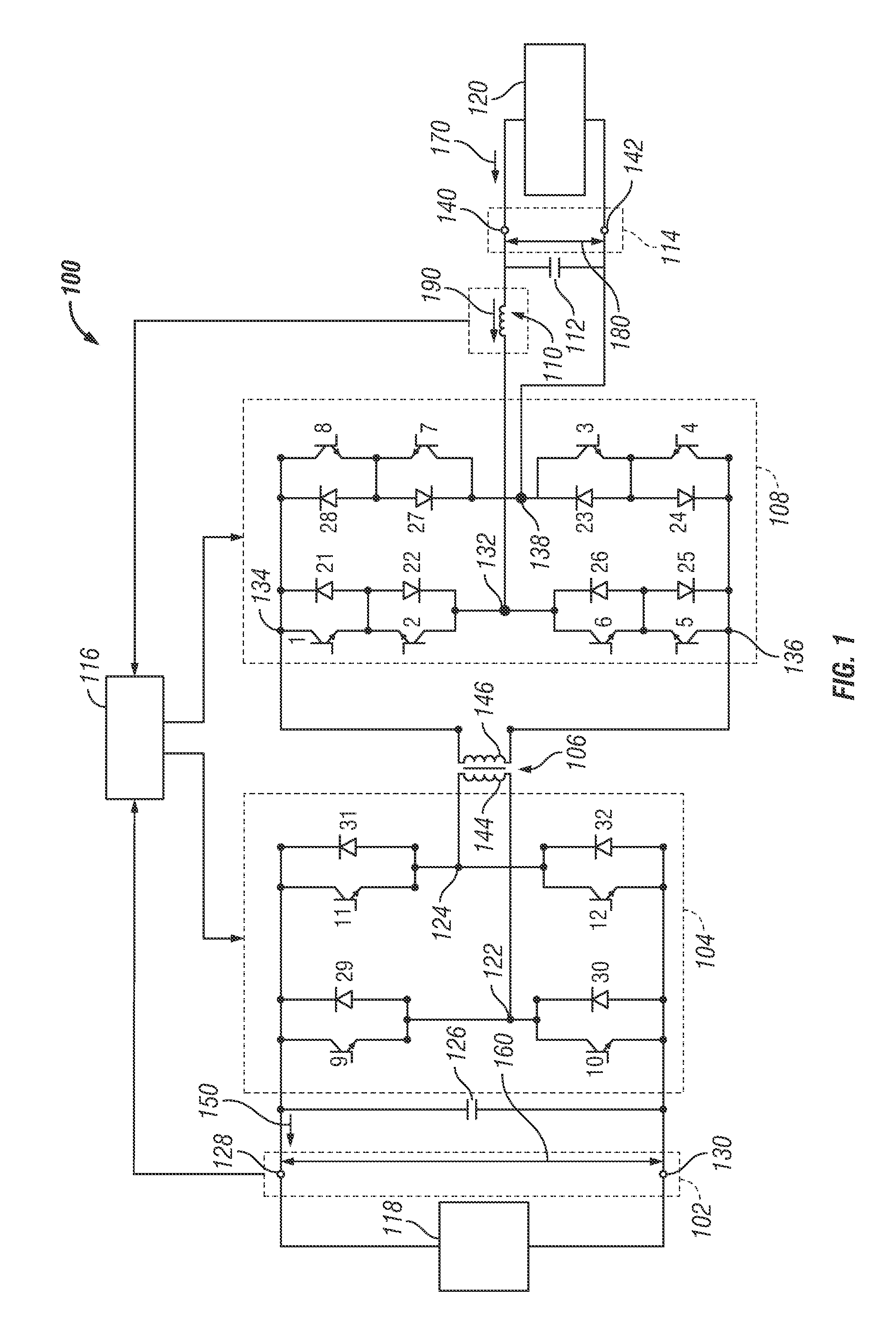
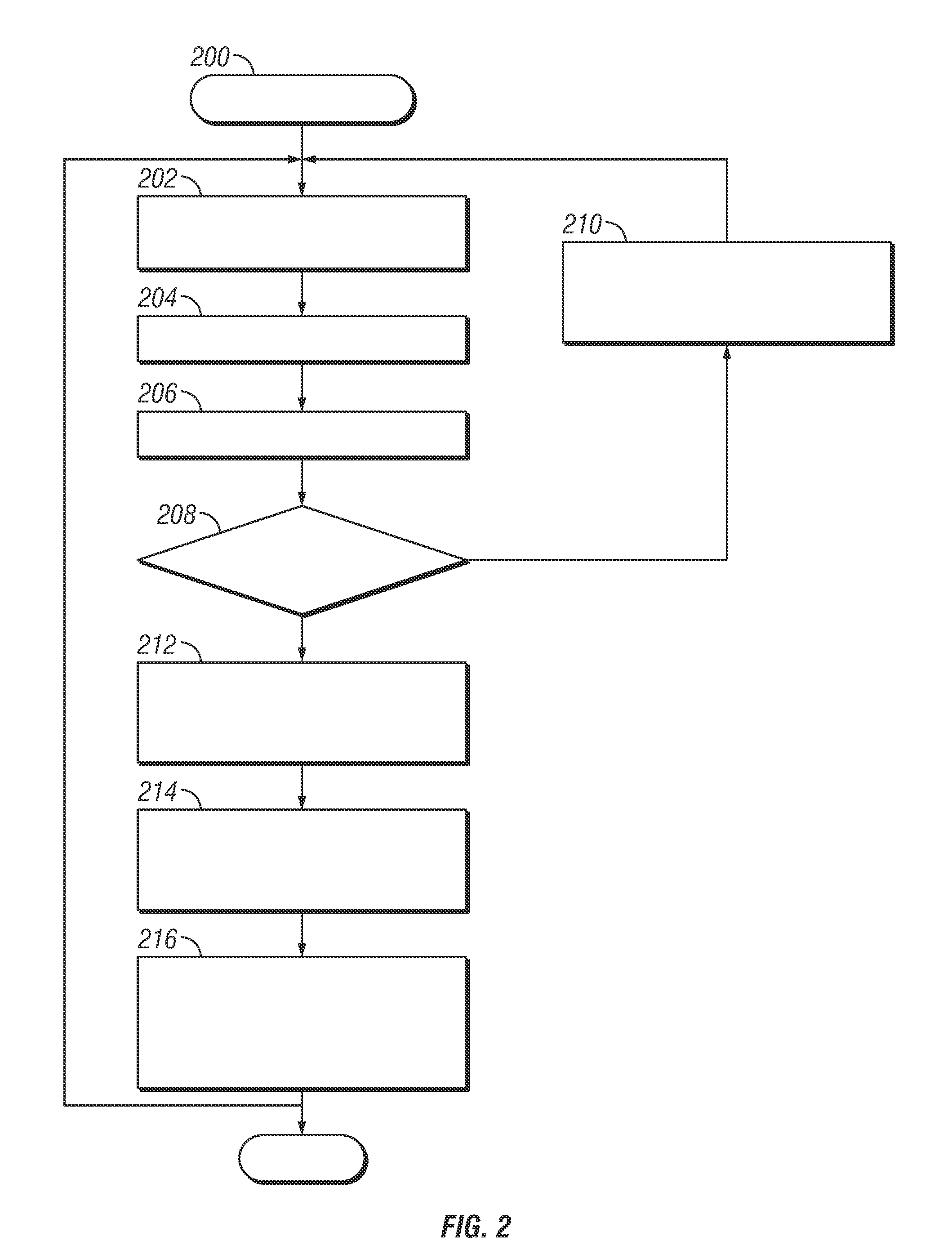
Systems and methods for reducing transient voltage spikes in matrix converters
a matrix converter and transient voltage technology, applied in the direction of electric variable regulation, process and machine control, instruments, etc., can solve the problems of loss of system components, undesirable and potentially damaging potential damage to the voltage spikes across components of the matrix converter, so as to reduce the magnitude of curren
- Summary
- Abstract
- Description
- Claims
- Application Information
AI Technical Summary
Problems solved by technology
Method used
Image

Examples
Embodiment Construction
[0014]The following detailed description is merely illustrative in nature and is not intended to limit the embodiments of the subject matter or the application and uses of such embodiments. As used herein, the word “exemplary” means “serving as an example, instance, or illustration.” Any implementation described herein as exemplary is not necessarily to be construed as preferred or advantageous over other implementations. Furthermore, there is no intention to be bound by any expressed or implied theory presented in the preceding technical field, background, brief summary or the following detailed description.
[0015]The following description refers to elements or nodes or features being “connected” or “coupled” together. As used herein, unless expressly stated otherwise, “connected” means that one element / node / feature is directly joined to (or directly communicates with) another element / node / feature, and not necessarily mechanically. Likewise, unless expressly stated otherwise, “coupl...
PUM
 Abstract
Description
Claims
Application Information