Video editing device and video editing system

a technology of video editing and video signal, applied in the direction of electronic editing digitised analogue information signals, instruments, image enhancement, etc., can solve the problems of significant lag in image information, degraded image information visibility, and detection time, and achieve the effect of suppressing the gap

Inactive Publication Date: 2012-01-19
RICOH KK
View PDF6 Cites 15 Cited by
  • Summary
  • Abstract
  • Description
  • Claims
  • Application Information

AI Technical Summary

Benefits of technology

[0007]According to the present invention, by comparing a frame at which the moving body no longer obstructs the object with each of frames at which the moving body obstructs the object, when the image information is extracted from the video of the object, it is thus possible to suppress a gap between a detected time point and a time point when the image information is drawn. Therefore, it is possible to provide a video editing device capable of suppressing a delay of a detection time with respect to a time when image information is drawn at the time of extracting the image information from a video of an object.
[0009]According to the present invention, the video editing device is caused to identify a frame at which drawing of image information is started by comparing a frame at which the moving body no longer obstructs the object with each of frames at which the moving body obstructs the object, thus when the image information is extracted from the video of the object, it is possible to suppress a gap between a detected time point and a time point when the image information is drawn.

Problems solved by technology

However, on a simply-shot video of the object, a moving body, such as a person who draws image information on the object, is captured, thus, when the drawn image information is obstructed by the moving body, the visibility of the image information is degraded.
However, in the above conventional technology, the entire range of areas where a lecturer area is moved in a certain period of time is extracted from the blackboard area and held, and an area that the lecturer area of a current frame is removed from the range is set down as a search area to be searched for update information on characters written on the blackboard, thus there is a problem that, for example, if the lecturer area is not moved over a long time, a detection time of characters written on the blackboard, i.e., image information lags significantly behind a time when the image information is actually drawn.

Method used


Image

  • Video editing device and video editing system
  • Video editing device and video editing system
  • Video editing device and video editing system

Examples


first embodiment

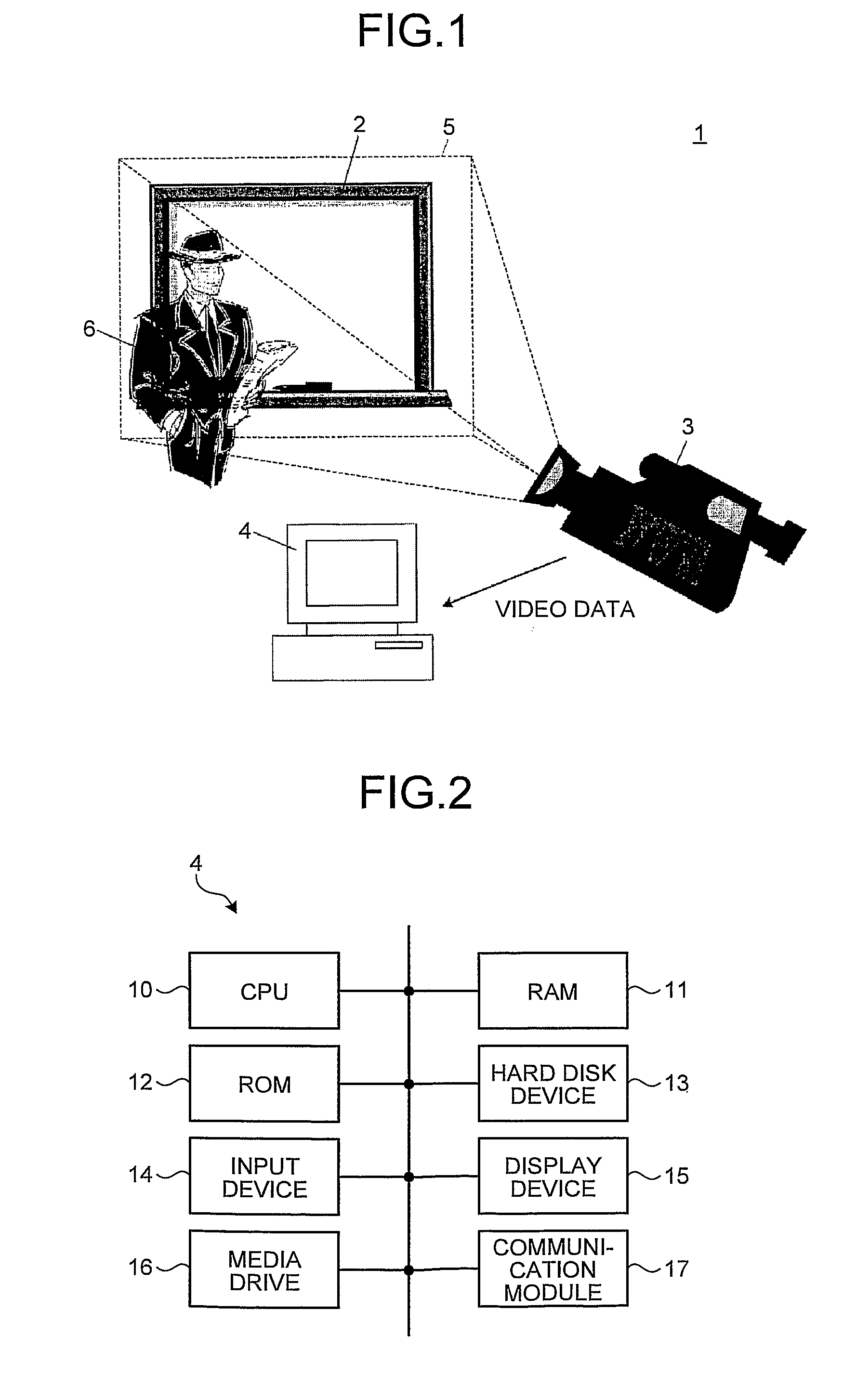
[0030]As shown in FIG. 1, a video editing system 1 according to a first embodiment of the present invention includes a whiteboard 2 as an object, a video shooting device 3 that shoots an area including the whiteboard 2, and a video editing device 4 that edits a video shot by the video shooting device 3.

[0031]In the present embodiment, an example where the whiteboard 2 is used as an object is explained; however, in the present invention, a blackboard, a projection screen, paper, and the like can be used as an object.

[0032]The video shooting device 3 is composed of a commonly-used video camera, and the video camera can be either the one that records a shot video on a storage medium, such as a magnetic disk, a magnetic tape, an optical disk, and a nonvolatile memory, or the one that converts a shot video into an electrical signal, a radio signal, or an optical signal and outputs the signal to an external device such as the video editing device 4. The video shooting device 3 is fixed wi...

second embodiment

[0074]A second embodiment of the present invention is achieved by changing the program executed by the CPU 10 of the video editing device 4 in the first embodiment of the present invention, and function blocks are specified in the same manner as the first embodiment, thus the second embodiment of the present invention is explained by using the video editing system 1 shown in FIG. 1.

[0075]In the first embodiment of the present invention, it is explained that the draw-frame identifying unit 21 extracts a circumscribed rectangle from a difference image. In the present embodiment, the draw-frame identifying unit 21 is configured to divide a difference image into cells of a relatively-large predetermined size (for example, 5 pixels×5 pixels or larger).

[0076]Furthermore, in the present embodiment, the draw-frame identifying unit 21 determines whether a corresponding area in a binarized post-detection frame matches a corresponding area in each of binarized detection frames for each cell co...

third embodiment

[0090]A third embodiment of the present invention is achieved by changing the program executed by the CPU 10 of the video editing device 4 in the first and second embodiments of the present invention, and function blocks are specified in the same manner as the first embodiment, thus the third embodiment of the present invention is explained by using the video editing system 1 shown in FIG. 1.

[0091]In the second embodiment of the present invention, it is explained that the draw-frame identifying unit 21 divides a difference image into cells of a relatively-large predetermined size. In the present embodiment, the draw-frame identifying unit 21 is configured to divide a difference image into cells of a relatively-small predetermined size (for example, smaller than 5 pixels×5 pixels). Incidentally, the size of these cells can be 1 pixel×1 pixel.

[0092]Furthermore, in the present embodiment, the draw-frame identifying unit 21 determines whether a corresponding area in a binarized post-det...


PUM


Abstract

A video editing device, which edits a video of an object on which image information is drawn, includes a moving-body-frame detecting unit that detects a frame on which a moving body obstructing the object is captured; a draw-frame identifying unit that identifies a frame at which drawing of the image information is started by comparing a post-detection frame that is an obstructed frame detected by the moving-body-frame detecting unit with each of detection frames that are not-obstructed frames detected by the moving-body-frame detecting unit; and a synthesis processing unit that performs a synthesis process of synthesizing image information included in the post-detection frame onto a frame anterior to the frame identified by the draw-frame identifying unit.

Description

TECHNICAL FIELD[0001]The present invention relates to a video editing device, and more particularly, to a video editing device for editing a video of an object on which image information is drawn and a video editing system including the video editing device.BACKGROUND ART[0002]Conventionally, there has been known a technology for recording image information drawn on an object, such as a whiteboard or a blackboard used in a meeting, a lecture, and the like, as a video. However, on a simply-shot video of the object, a moving body, such as a person who draws image information on the object, is captured, thus, when the drawn image information is obstructed by the moving body, the visibility of the image information is degraded.[0003]For resolving such degradation of the visibility of the image information, there has been developed a technology for extracting contents written on a blackboard as an object from a blackboard video obtained by recording a video of the blackboard, in such a m...

Claims


Application Information

Patent Timeline
Patent Type & Authority Applications(United States)
IPC IPC(8): H04N5/91
CPCG11B27/034G06T7/2006G06T2207/30196G06T7/2053G06T2207/10016G06T5/005G06T7/215G06T7/254
Inventor KASUYA, YUUJI
Owner RICOH KK
Why Eureka
Try Eureka