Connector
- Summary
- Abstract
- Description
- Claims
- Application Information
AI Technical Summary
Benefits of technology
Problems solved by technology
Method used
Image
Examples
first embodiment
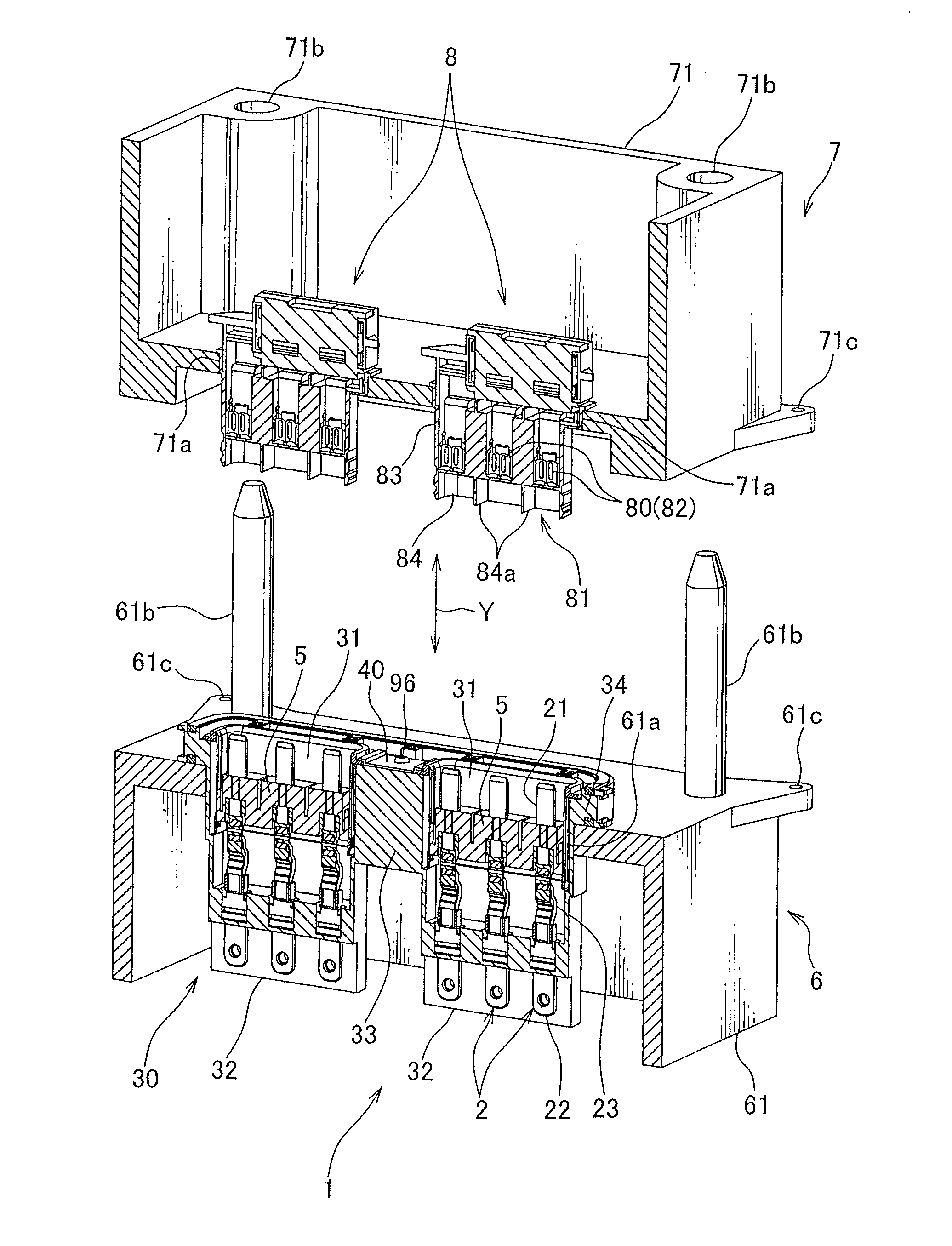
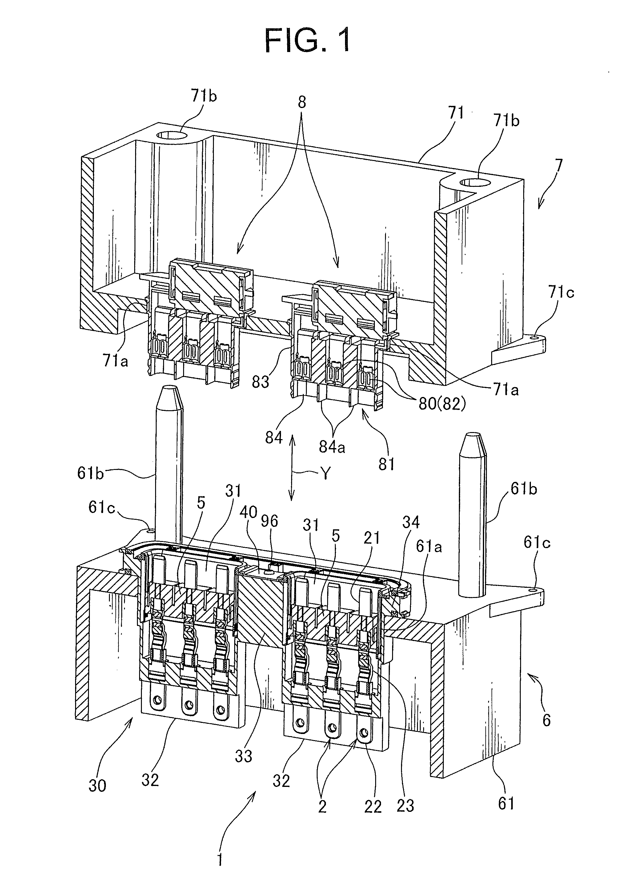
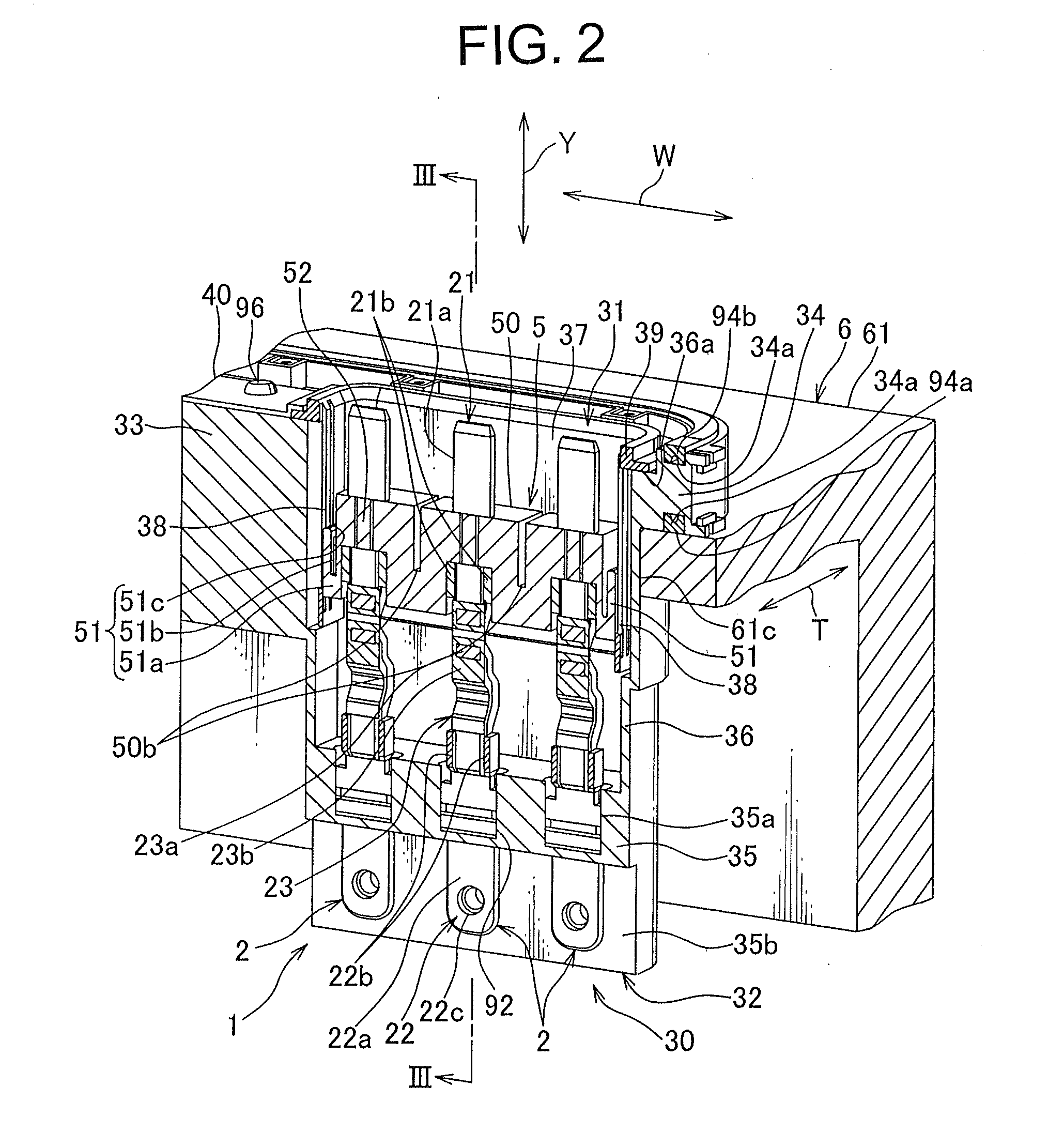
[0085]A connector according to a first embodiment of the present invention will be explained with reference to FIGS. 1 to 3.
[0086]As shown in FIG. 1, a pair of connectors 1 is attached to a case 61 of a motor 6 mounted on an electric vehicle or a hybrid vehicle, and fitted with, namely, electrically connected to a pair of mating connectors 8 attached to a case 71 of an ECU (Electric Control Unit) 7. Namely, when the ECU 7 is mounted on the motor 6, the pair of connectors 1 is directly connected to the pair of mating connectors 8 integrally provided with the ECU 7.
[0087]Further, the pair of mating connectors 8 is respectively attached to a pair of connector receiving holes 71a provided on the case 71 of the ECU 7. The connector receiving hole 71a penetrates an outer wall of the case 71, and is formed in a shape following an outer surface of a housing main body 83 of a later-described housing 81 of the mating connector 8. Further, a positioning hole 71b into which a boss 61b of the mo...
second embodiment
[0127]A connector 101 according to a second embodiment of the present invention will be explained with reference to FIGS. 4 to 7.
[0128]As shown in FIG. 5, the connector 101 is fitted with a mating connector 111 to be electrically connected to the mating connector 111. Further, the mating connector 111 includes: a tubular housing 113; and a terminal 112 received in the housing 113. The terminal 112 is made of a metallic plate, and formed in a tubular shape, namely, a female type. Further, a plurality of spring pieces 112a elastically deformable along a radial direction of the terminal 112 is provided on the terminal 112 by forming a plurality of slits on an outer wall of the terminal 112. These spring pieces 112a elastically contact a first electric connecting part 121 of a later-described terminal 102 of the connector 101, and press the first electric connecting part 121 inward.
[0129]Further, an arrow Y shown in FIGS. 4 to 7 indicates a fitting direction of the mating connector 111 ...
third embodiment
[0151]A connector 201 according to a third embodiment of the present invention will be explained with reference to FIGS. 8 and 9.
[0152]The connector 201 is fitted with a mating connector (not shown) and electrically connected to the mating connector. Further, an arrow Y of FIGS. 8 and 9 indicates a fitting direction between the connector 201 and the mating connector, and an arrow X indicates a direction perpendicular to the fitting direction. As shown in FIGS. 8 and 9, the connector 201 includes: a terminal 202; an inner housing 204 receiving and holding a later-described first electric connecting part 221 of the terminal 202; and an outer housing 203 receiving the terminal 202 and the inner housing 204.
[0153]The terminal 202 is provided with the first electric connecting part 221 for electrically connected to the terminal of the mating connector, a second electric connecting part 222 for electrically connected to a not-shown terminal (for example, a terminal as a component of an el...
PUM
 Abstract
Description
Claims
Application Information
 - R&D
- Intellectual Property
- Life Sciences
- Materials
- Tech Scout
- Unparalleled Data Quality
- Higher Quality Content
- 60% Fewer Hallucinations
Browse by: Latest US Patents, China's latest patents, Technical Efficacy Thesaurus, Application Domain, Technology Topic, Popular Technical Reports.
© 2025 PatSnap. All rights reserved.Legal|Privacy policy|Modern Slavery Act Transparency Statement|Sitemap|About US| Contact US: help@patsnap.com


