Gas turbine with improved part load emissions behavior

a gas turbine and emission behavior technology, applied in the direction of turbine/propulsion engine ignition, combustion control, lighting and heating apparatus, etc., can solve the problems of high co (carbon monoxide) emissions, the possibility of running for longer operating periods at low part load is increasingly also required, and the operation of longer periods at low part load cannot be realized, so as to achieve high fuel flow rate and high maximum air ratio max

Inactive Publication Date: 2012-01-26
ANSALDO ENERGIA IP UK LTD
View PDF1 Cites 65 Cited by
  • Summary
  • Abstract
  • Description
  • Claims
  • Application Information

AI Technical Summary

Benefits of technology

[0055]For example, a burner lance with a low flow rate is arranged downstream of a burner of the first combustor which has a high fuel flow rate. The locally high flow rate in the first combustor leads to a locally high exit temperature from the first combustor and therefore to a locally increased inlet temperature in the upstream-disposed burners of the second combustor. In proportion to the increased inlet temperature for this burner, the reaction speed of fuel which is injected into it is higher than on average to all the burners. Therefore, it can be operated with a locally higher maximum air ratio λmax. A lance with a low flow coefficient can be installed at this position for matching to the first combustor.

Problems solved by technology

The aforementioned known operating concepts, however, at low part load, especially within the range of about 20% to 50% of the relative load, can lead to high CO (carbon monoxide) emissions.
Within the limits of a flexible power plant operation, however, the possibility of running for longer operating periods at low part load is increasingly also required.
A longer operation at low part load can only be realized if the CO emissions also remain at a low level.
In addition to high acquisition costs, these lead to pressure losses in the exhaust gas system of the gas turbine and to forfeiture of power and efficiency which is associated therewith.
In practice, however, as a result of the quick closing of the row of variable compressor inlet guide vanes and as a result of the engaging and disengaging of the second combustor, overswings of the TIT of the high-pressure turbine can occur.
Each limitation to a cold adjacent burner potentially leads to increased CO emissions, which is why the number of groups of cold burner is to be minimized.
Homogenous combustion processes can lead to pulsations in annular combustors.
At high load, this leads to a desired inhomogeneity in the annular combustor.
At low load, this inhomogeneity, however, leads to an over-proportional increase of CO production of the at least one restricted burner.
This especially also leads to different pressure losses and flow rates during operation.
A typical example is the installation of fuel lances with high flow rate in burners with large cross section and correspondingly low pressure loss.

Method used


Image

  • Gas turbine with improved part load emissions behavior
  • Gas turbine with improved part load emissions behavior
  • Gas turbine with improved part load emissions behavior

Examples


Embodiment Construction

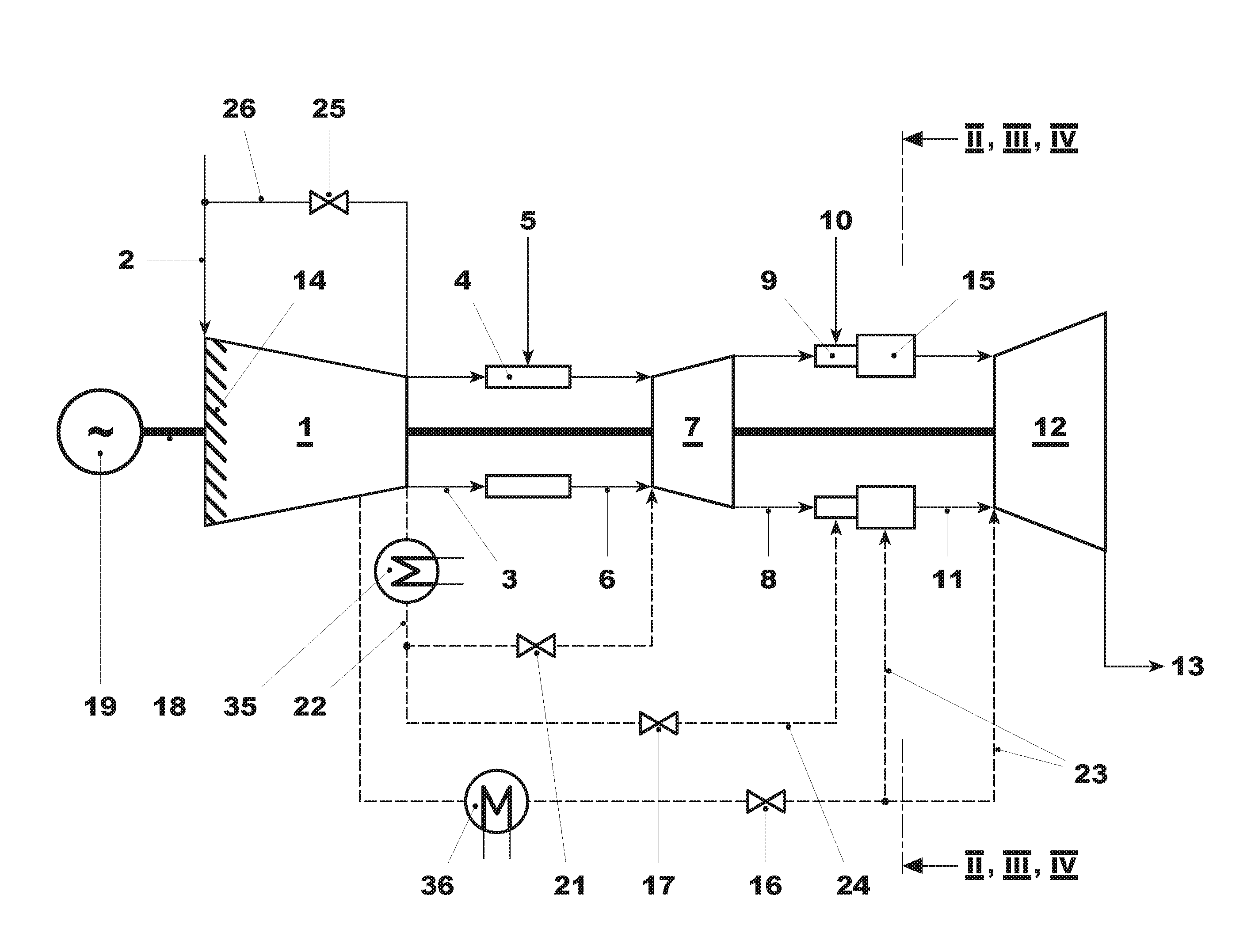
[0072]FIG. 1 shows a gas turbine with sequential combustion useful for implementing methods as described herein. The gas turbine includes a compressor 1, a first combustor 4, a first turbine 7, a second combustor 15, and a second turbine 12. Typically, it includes a generator 19 which, at the cold end of the gas turbine, that is to say at the compressor 1, is coupled to a shaft 18 of the gas turbine.

[0073]A fuel, gas, or oil is introduced via a fuel feed 5 into the first combustor 4, mixed with air which is compressed in the compressor 1, and combusted. The hot gases 6 are partially expanded in the subsequent first turbine 7, performing work.

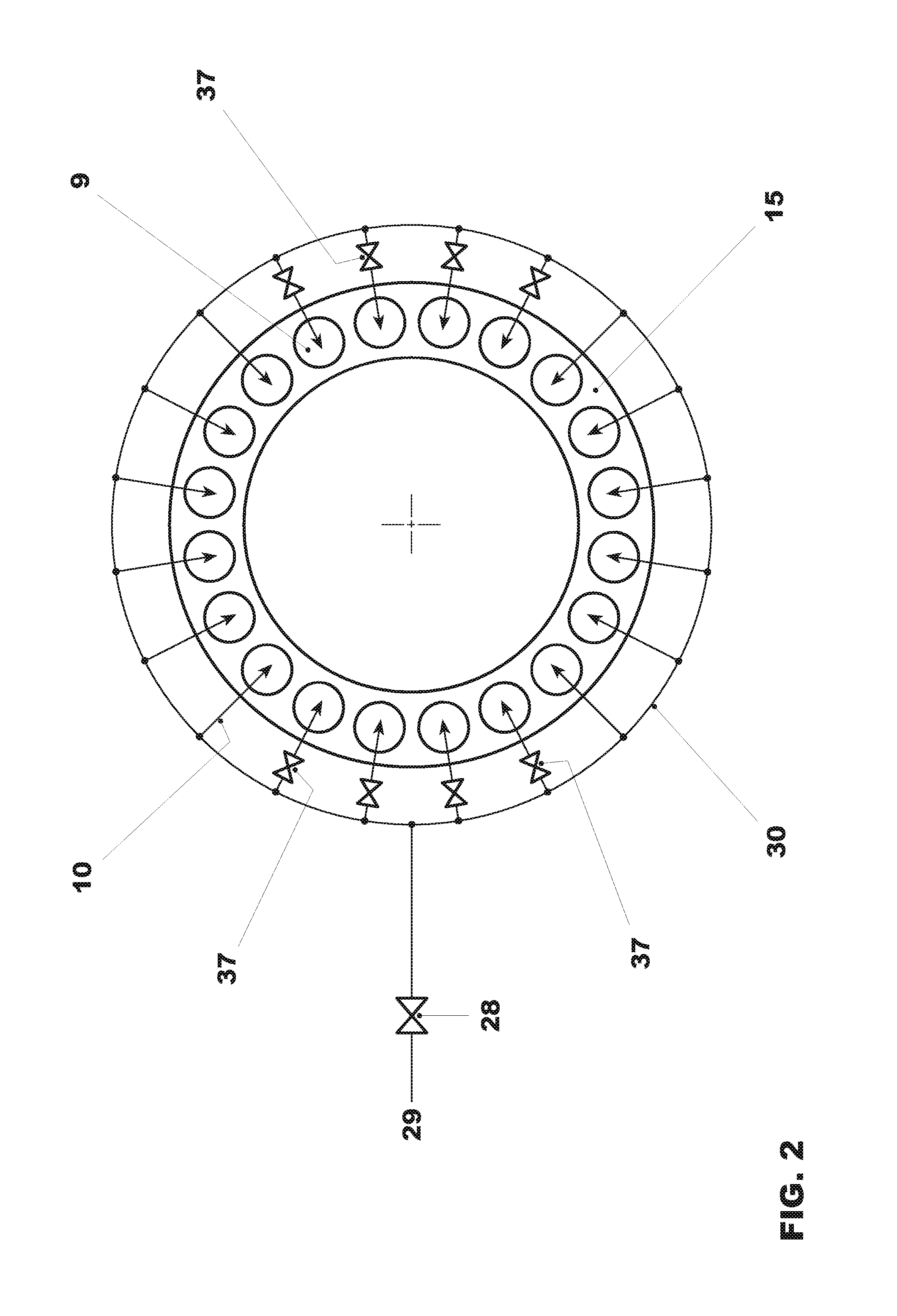
[0074]As soon as the second combustor is in operation, additional fuel, via a fuel feed 10, is added to the partially expanded gases 8 in burners 9 of the second combustor 15 and combusted in the second combustor 15. The hot gases 11 are expanded in the subsequent second turbine 12, performing work. The exhaust gases 13 can be beneficially fed t...


PUM


Abstract

In a method for the low-CO emissions part load operation of a gas turbine with sequential combustion, the air ratio (λ) of the operative burners (9) of the second combustor (15) is kept below a maximum air ratio (λmax) at part load In order to reduce the maximum air ratio (λ), a series of modifications in the operating concept of the gas turbine are carried out individually or in combination. One modification is an opening of the row of variable compressor inlet guide vanes (14) before engaging the second combustor (15). For engaging the second combustor, the row of variable compressor inlet guide vanes (14) is quickly closed and fuel is introduced in a synchronized manner into the burner (9) of the second combustor (15). A further modification is the deactivating of individual burners (9) at part load.

Description

[0001]This application is a Continuation of, and claims priority under 35 U.S.C. §120 to, International application no. PCT / EP2010 / 053171, filed 12 Mar. 2010, and claims priority therethough under 35 U.S.C. §§119, 365 to Swiss application no. 00536 / 09, filed 1 Apr. 2009, the entireties of which are incorporated by reference herein.BACKGROUND[0002]1. Field of Endeavor[0003]The invention relates to a method for operating a gas turbine with sequential combustion and low CO emissions.[0004]2. Brief Description of the Related Art[0005]Gas turbines with sequential combustion have been successful in commercial operation for some time now. In them, compressed air is combusted with fuel in a first combustor, and a first turbine, referred to as the high-pressure turbine, is exposed to admission of hot gases. The temperature of the hot gases which discharge from the high-pressure turbine is increased again in a second combustor as a result of renewed addition of fuel and its combustion, and a ...

Claims


Application Information

Patent Timeline
Patent Type & Authority Applications(United States)
IPC IPC(8): F02C3/14F02C7/228F02C7/00
CPCF02C6/003F23C6/042F23N1/022F02C9/26F23N2041/20F23R7/00Y02E20/16F23N2037/02F23R2900/03341F23N2237/02F23N2241/20
Inventor EROGLU, ADNANKNAPP, KLAUSFLOHR, PETERKNOPFEL, HANS PETERGENG, WEIQUN
Owner ANSALDO ENERGIA IP UK LTD
Why Eureka
Try Eureka