Thermoelectric Conversion Module

a technology of thermoelectric conversion module and thermoelectric converter, which is applied in the direction of photovoltaics, electrical apparatus, and semiconductor devices, can solve the problems of binding portion breakage, and achieve the effects of preventing heat dissipation, reducing thermoelectric conversion efficiency, and preventing pressing damag

Inactive Publication Date: 2012-01-26
SUMITOMO CHEM CO LTD
View PDF0 Cites 26 Cited by
  • Summary
  • Abstract
  • Description
  • Claims
  • Application Information

AI Technical Summary

Benefits of technology

[0016]The present invention prevents the damage of the pressing means by heat, prevents the heat dissipation through the pressing means on the higher-temperature side and the reduction of thermoelectric conversion efficiency due to it, and achieves better electrical conduction even in the case where the thermoelectric conversion elements and the electrodes are not cemented through a binder.

Problems solved by technology

In a thermoelectric conversion module wherein thermoelectric conversion elements and electrodes are cemented through a binder such as a solder or a brazing material, thermal stress occurs between the thermoelectric conversion elements and the electrodes on the higher-temperature side of the thermoelectric conversion module because of the difference between the thermal expansion coefficients of the thermoelectric conversion elements and the electrodes, so as to result in breakage of binding portions in some cases.

Method used


Image

  • Thermoelectric Conversion Module
  • Thermoelectric Conversion Module
  • Thermoelectric Conversion Module

Examples


first embodiment

Thermoelectric Conversion Module of First Embodiment

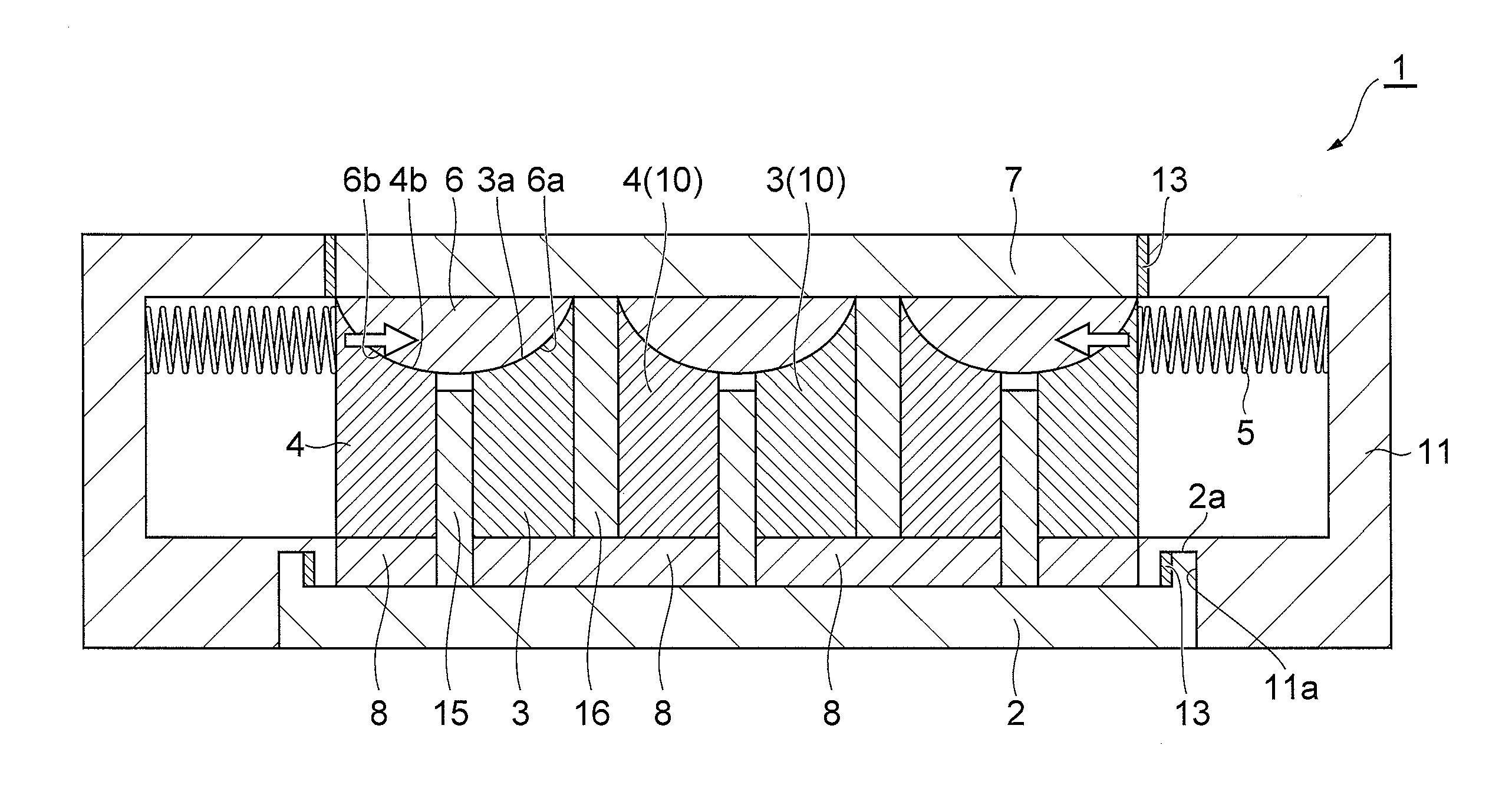
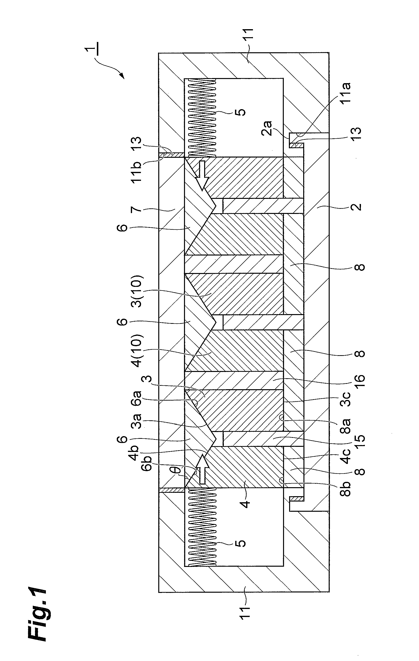
[0022]FIG. 1 is a schematic cross-sectional view of the thermoelectric conversion module according to the first embodiment. The thermoelectric conversion module 1 is provided with a thermoelectric conversion section having a lower-temperature side substrate 2, a higher-temperature side substrate 7, lower-temperature side electrodes 6, higher-temperature side electrodes 8, p-type thermoelectric conversion elements 3, n-type thermoelectric conversion elements 4, insulating members 15, and insulating members 16, pressing members 5, and substrate holding members 11.

[0023][Thermoelectric Conversion Section]

[0024]In the thermoelectric conversion section, the lower-temperature side substrate 7 and the higher-temperature side substrate 2 oppose to each other and are arranged approximately in parallel. The lower-temperature side electrodes 6 are arranged in a non-cemented state on the surface of the lower-temperature side substrate 7 opposi...

second embodiment

Thermoelectric Conversion Module of Second Embodiment

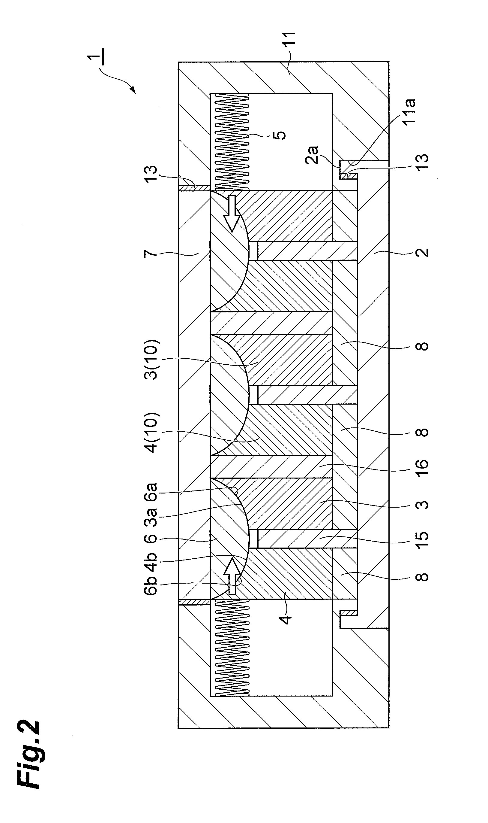
[0061]The following will describe the thermoelectric conversion module of the second embodiment shown in FIG. 2. The thermoelectric conversion module of the second embodiment is different from the first embodiment in that the slope faces 6a, 6b of the lower-temperature side electrodes 6 are not flat faces but convex faces and, corresponding thereto, the faces 3a of the p-type thermoelectric conversion elements 3 and the faces 4b of the n-type thermoelectric conversion elements 4 are concave faces. As shown in FIG. 2, in the case where the slope faces of the lower-temperature side electrodes 6 are convex faces, the steric shape of the lower-temperature side electrodes 6 is, for example, a semispherical shape, or a shape obtained by cutting a circular cylinder by a plane parallel to its axis.

[0062]Here, that the angle of each slope face 6a, 6b of the lower-temperature side electrode 6 with respect to the surface of the lower-tempera...

third embodiment

Thermoelectric Conversion Module of Third Embodiment

[0063]The following will describe the thermoelectric conversion module of the third embodiment shown in FIG. 3. The thermoelectric conversion module 1 of the third embodiment is different from the first embodiment in that the slope faces 6a, 6b of the lower-temperature side electrodes 6 are not flat faces but concave faces and, corresponding thereto, the faces 3a of the p-type thermoelectric conversion elements 3 and the faces 4b of the n-type thermoelectric conversion elements 4 are convex faces. As shown in FIG. 3, in the case where the slope faces of each lower-temperature side electrode 6 are concave faces, the steric shape of the lower-temperature side electrode 6 is, for example, one having a pair of grooves of an arc-like cross section, or one having a pair of semispherical concave faces. In the third embodiment, each pressing member 5 presses the thermoelectric conversion element 10 through a spacer 17.

[0064]Here, that the ...


PUM


Abstract

A pressing member is prevented from being damaged by heat, heat dissipation through the pressing member on the higher-temperature side and reduction in thermoelectric conversion efficiency due to it are suppressed, and good electrical conduction is achieved even if thermoelectric conversion elements and electrodes are not cemented through a binder. A lower-temperature side electrode 6 is projecting toward a higher-temperature side substrate 8 and the lower-temperature side electrode 6 is formed with slope faces 6a, 6b, and an angle θ of each of the slope face to a surface of a lower-temperature side substrate 7 is an acute angle. A face 3a of a p-type thermoelectric conversion element 3 in contact with the lower-temperature side electrode 6 is along one slope face 6a of the lower-temperature side electrode and a face 4b of an n-type thermoelectric conversion element 4 in contact with the lower-temperature side electrode 6 is along the other slope face 6b of the lower-temperature side electrode 6; the p-type thermoelectric conversion element 3 and the n-type thermoelectric conversion element 4 are in contact with the lower-temperature side electrode 6 through the respective slope faces; a pressing member 5 presses a portion on the lower-temperature side substrate side of an outside thermoelectric conversion element 10, toward the other outside thermoelectric conversion element 10.

Description

TECHNICAL FIELD[0001]The present invention relates to a thermoelectric conversion module.BACKGROUND ART[0002]In a thermoelectric conversion module wherein thermoelectric conversion elements and electrodes are cemented through a binder such as a solder or a brazing material, thermal stress occurs between the thermoelectric conversion elements and the electrodes on the higher-temperature side of the thermoelectric conversion module because of the difference between the thermal expansion coefficients of the thermoelectric conversion elements and the electrodes, so as to result in breakage of binding portions in some cases. In order to solve this problem, there are attempts to achieve good electrical conduction without cementing the thermoelectric conversion elements and the electrodes in the thermoelectric conversion module by soldering or brazing. Patent Literature 1 discloses the thermoelectric conversion module provided with pressing members to apply a pressing load from side faces ...

Claims


Application Information

Patent Timeline
Patent Type & Authority Applications(United States)
IPC IPC(8): H01L35/04
CPCH01L35/06H01L2924/0002H01L2924/00H10N10/813
Inventor SAWABE, YOSHINARIHIROYAMA, YUICHI
Owner SUMITOMO CHEM CO LTD
Why Eureka
Try Eureka