Biosafety cabinetry

a biosafety cabinet and biohazard technology, applied in the field of biosafety cabinets, can solve the problems of restricted operation, restricted workspace location, and restricted performance of operators, and achieve the effects of workability of operation, and preventing chemical contamination or biological contamination

Active Publication Date: 2012-01-26
HITACHI IND EQUIP SYST CO LTD
View PDF6 Cites 17 Cited by
  • Summary
  • Abstract
  • Description
  • Claims
  • Application Information

AI Technical Summary

Benefits of technology

[0009]According to the present invention, a biosafety cabinet has gloves movably attached to a front cover thereof, so that the workability of operation to be performed, while preventing chemical contamination or biological contamination, using the gloves can be improved. Also, the workability of operation to be performed, while taking measures against biohazards or chemical hazards, using the gloves attached to the biosafety cabinet can be improved.

Problems solved by technology

In this type of biosafety cabinet, the positions of the gloves worn by the operator are fixed, so that there are cases in which the location in the workspace where the material to be handled can be placed is restricted or in which the operator's performance is restricted depending on his / her body type.

Method used


Image

  • Biosafety cabinetry
  • Biosafety cabinetry
  • Biosafety cabinetry

Examples


first embodiment

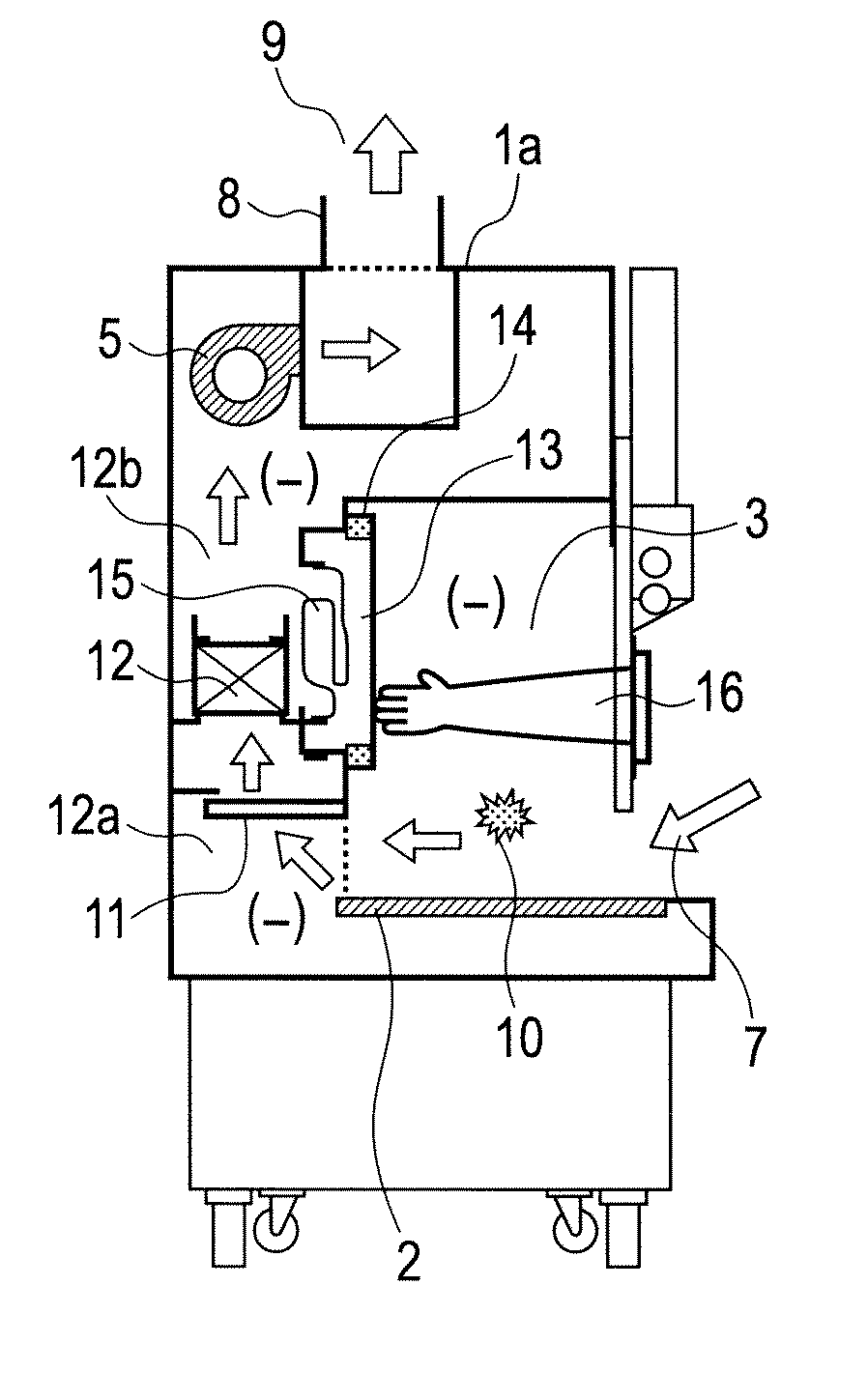
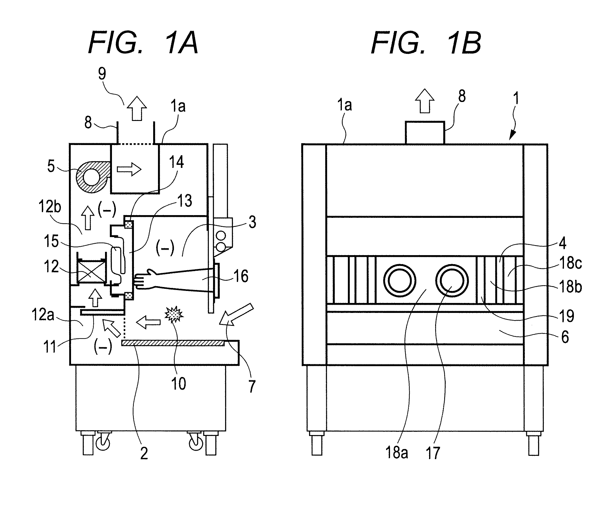
[0022]With reference to FIGS. 1A-1B to FIGS. 5A-5D, a first embodiment of a chemical hazard safety cabinet according to the present invention will be described below. FIGS. 1A and 1B show a chemical hazard safety cabinet 1, FIG. 1A being a longitudinal sectional view and FIG. 1B being a front view. The cabinet 1 has a front shutter 4 vertically movably installed on a front of a workspace 3 formed inside a main body case 1a. When the front shutter 4 is lifted, a front opening 6 of the workspace 3 appears below the front shutter 4. When the front shutter 4 is in a lowered position, the front opening 6 is closed.

[0023]A HEPA filter path 12a is formed in upper and lower portions, behind the workspace 3, of the interior of the main body case 1a. The HEPA filter path 12a is used to filter contaminants and dust generated in the workspace 3 for air purification. In an upper portion of space behind the workspace 3, a plastic bag 15 for accommodating the contaminated HEPA filter 12 is held. A...

second embodiment

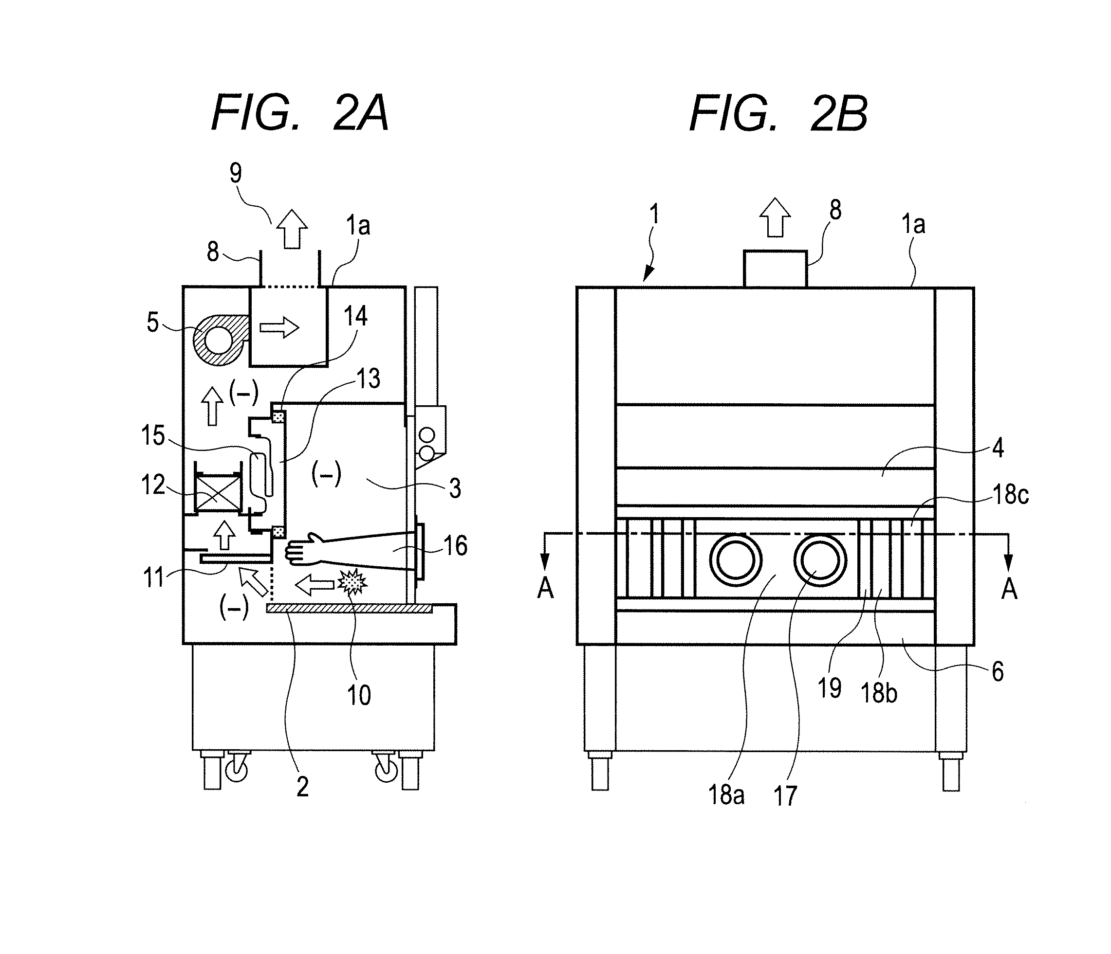
[0045]With reference to FIGS. 6A, 6B, and 7, a second embodiment of a chemical hazard safety cabinet according to the present invention will be described below. FIGS. 6A and 6B show a chemical hazard safety cabinet 1, FIG. 6A being a longitudinal sectional view and FIG. 6B being a front view. FIG. 7 is a sectional view, taken along line E-E in FIG. 6B, of a front shutter 4 included in the cabinet 1 shown in FIGS. 6A and 6B. The second embodiment differs from the first embodiment in that a front opening 6 is provided with a glove panel 20. Excepting this difference, the configuration of the second embodiment is the same as that of the first embodiment.

[0046]Referring to FIGS. 6A and 6B, a grooved holding member 22 is provided on each side of the front opening 6. The glove panel 20 is held, at both sides thereof, by the grooved holding members 22. The grooved holding members 22 are positioned inwardly of the front shutter 4, i.e. to be more inside a workspace 3 than the front shutter ...

third embodiment

[0051]With reference to FIGS. 8A, 8B, and 9, a third embodiment of a chemical hazard safety cabinet according to the present invention will be described below. FIGS. 8A and 8B show a chemical hazard safety cabinet 1, FIG. 8A being a longitudinal sectional view and FIG. 8B being a front view. FIG. 9 is a sectional view, taken along line F-F in FIG. 8B, of a front shutter 4 included in the cabinet 1 shown in FIGS. 8A and 8B.

[0052]The third embodiment differs from the first embodiment in that glove ports 17 are provided not in a central small window 18a but in left and right small windows 18b. No glove port is provided in the small window 18a. The central small window 18a is positioned between the left and right small windows 18b. Distance G between the two gloves 16 can be changed.

[0053]The small window 18a and the small windows 18b are arranged to be partly overlapped. The small windows 18b and the small windows 18c are also arranged to be partly overlapped on each side of the small ...


PUM


Abstract

The workability of operation to be performed, while preventing chemical or biological contamination, using a biosafety cabinet and gloves attached to the cabinet is improved. A biosafety cabinet includes a workspace formed in a main body cabinet thereof. Air in the workspace is discharged to outside via filters. A vertically movable front shutter is disposed on a front of the workspace. A front opening is formed below the front shutter to be at a front of the workspace. The front shutter includes plural laterally movable small windows which are overlapped like layered sliding doors. One of the plural small windows is provided, on the workspace side thereof, with a pair of glove ports to which a pair of gloves for use in operation in the workspace can be air-tightly attached.

Description

CLAIM OF PRIORITY[0001]The present application claims priority from Japanese application 2010-163031 filed on Jul. 20, 2010, the content of which is hereby incorporated by reference into this application.BACKGROUND OF THE INVENTION[0002]The present invention relates to draft chambers, class II biohazard safety cabinets, and chemical hazard safety cabinets (may hereinafter be referred to collectively as “biosafety cabinets”) and, more particularly, to a biosafety cabinet suitable for use in handling contaminants in a workspace formed therein.[0003]Draft chambers, cabinets for use in the nanotechnological field, and chemical hazard safety cabinets (may hereinafter be referred to collectively as “biosafety cabinets”) include, in many cases, an internal workspace where operation can be performed. A cabinet having such a workspace includes a front shutter and a front opening formed below the front shutter. An operator can extend his / her arms through the front opening into the cabinet and...

Claims


Application Information

Patent Timeline
Patent Type & Authority Applications(United States)
IPC IPC(8): B25J21/02
CPCB25J21/02
Inventor ONO, KEIICHIKODAMA, TOMOTAKA
Owner HITACHI IND EQUIP SYST CO LTD
Why Eureka
Try Eureka