Energy storage and vehicle charging system and method of operation

Inactive Publication Date: 2012-01-26
CONSOL EDISON OF NEW YORK
View PDF8 Cites 43 Cited by
  • Summary
  • Abstract
  • Description
  • Claims
  • Application Information

AI Technical Summary

Problems solved by technology

Electrical energy is transferred from the energy storage device when there is a disruption in the transfer of electrical energy from the source.

Method used


Image

  • Energy storage and vehicle charging system and method of operation
  • Energy storage and vehicle charging system and method of operation
  • Energy storage and vehicle charging system and method of operation

Examples


Embodiment Construction

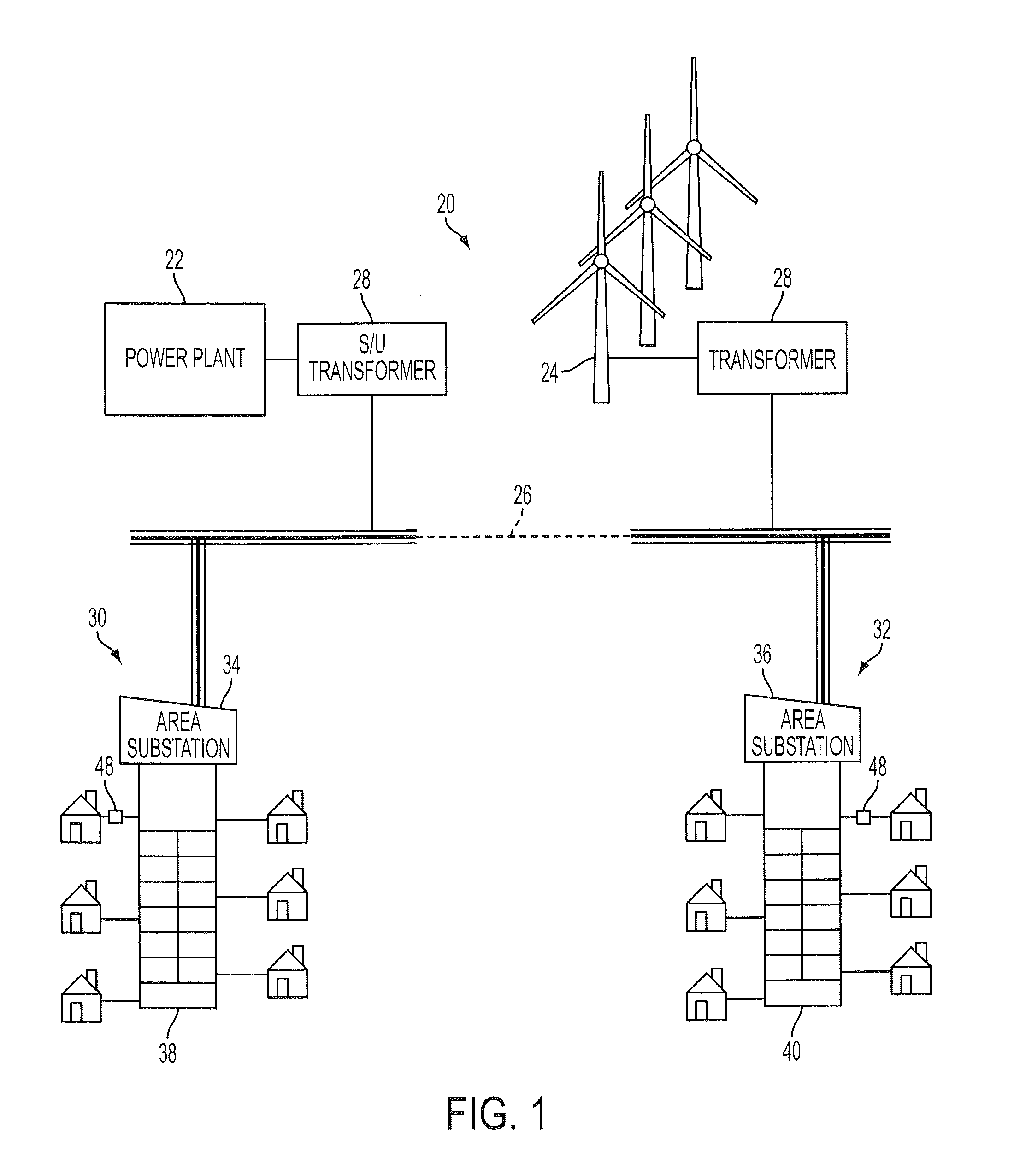
[0020]FIG. 1 illustrates an exemplary embodiment of a utility electrical transmission and distribution system 20. The system 20 includes one or more electric power generation facilities 22 connected in parallel to a main transmission system 26 by multiple step-up transformers 28. The power generators 22 may include, but are not limited to: coal, nuclear, natural gas, or incineration power plants. Additionally, the system 20 may include power generation facilities 24 that utilize renewable energy sources, such as hydroelectric, solar, or wind turbine power generators. The step-up transformers 28 increase the voltage from that produced by the power generators 22, 24 to a high voltage, such as 138 kV for example, to allow long distance transmission of the electric power over main transmission system 26. It should be appreciated that additional components such as transformers, switchgear, fuses and the like (not shown) may be incorporated into the transmission and distribution system 20...


PUM


Abstract

An energy storage system for a substation on an electrical power network is provided. The energy storage system is coupled to receive and store electrical power. The stored electrical power may then be used to either charge vehicles or meeting the needs of other discretionary or interruptible loads with an electric propulsion, or to provide electrical power a feeder connected to essential service loads such as police stations, hospitals and traffic control. In one embodiment, the substation also utilizes the energy storage system in a peak shaving mode of operation.

Description

BACKGROUND OF THE INVENTION[0001]The subject matter disclosed herein relates to a system and method for storing excess electrical production capacity for use as a flexible energy source, and in particular to a system that may be used for charging electric based vehicles and integrating solar and wind energy resources for providing electrical power to important infrastructure assets.[0002]The current electrical power network has an expansive infrastructure that delivers electrical power produced by a few large centrally located power generation facilities to a large number of geographically dispersed consumers. In general, the electric power network can be broken into two portions, a transmission system and, a distribution system. The transmission system transfers high voltage (e.g. >135 kV) electrical power over long distances from the power generation plant to the area where the energy will be consumed. The electrical power is transferred at high voltages to minimize the losses ...

Claims


Application Information

Patent Timeline
Patent Type & Authority Applications(United States)
IPC IPC(8): H02J7/00
CPCB60L11/1824Y02T10/7291H01M10/44H01M10/46H02J3/32H02J7/0027H02J7/0054Y02T10/7005Y02T10/7055Y02T10/7088Y02T90/128Y02T90/14Y02T90/163Y02E70/30Y04S10/126Y02E60/721B60L3/0069B60L3/04B60L11/1816B60L11/184B60L11/1846B60L2210/30B60L2210/40B60L2230/26B60L2230/28B60L2230/30B60L2230/32B60L2230/40B60L2240/72Y02T10/7241Y02T90/168Y02T90/169Y02T90/121Y02T90/127Y04S30/12Y04S30/14H02J3/383H02J3/386Y02E10/563Y02E10/763H02J3/382B60L11/1844B60L53/64B60L53/63B60L53/65B60L53/56B60L53/54B60L53/53B60L53/55B60L53/68H02J7/342B60L53/18H02J2300/40H02J2300/28H02J2300/20H02J2300/24H02J3/381Y02E10/56Y02E10/76Y02E60/00Y02T10/70Y02T10/7072Y02T10/72Y02T90/12Y02T90/167Y02T90/16Y02E60/10H02J7/0045H02J3/322H02J2310/48
Inventor KRESSNER, A. ARTHUR
Owner CONSOL EDISON OF NEW YORK
Why Eureka
Try Eureka