Modular LED display structure with connecting edge banding to connect each other

a module-type led and display structure technology, applied in the direction of static indicating devices, identification means, instruments, etc., can solve the problems of increasing manufacturing costs, difficult maintenance or repair, and unable to meet human visual needs, and achieve the effect of convenient taking and assembling

Inactive Publication Date: 2012-01-26
APA ELECTRONICS
View PDF15 Cites 68 Cited by
  • Summary
  • Abstract
  • Description
  • Claims
  • Application Information

AI Technical Summary

Benefits of technology

[0007]To solve the aforesaid problems of the prior art, the present invention provides a modular LED display structure with connecting edge banding to connect each other. The modular LED display of the present invention is easy to take and to assemble to develop a large led display.
[0008]Accordingly, the present invention discloses a LED display structure having a plurality of LED module plates connected each other. The LED module plates includes a flexible PCB (printed circuit board), a plurality of protective plates, a plurality of full-color LED units and at least one connecting edge banding. The full-color LED units are arranged on the flexible PCB to form a matrix and at least one transmission line connects thereof. The protective plates pasted on the back side of the flexible PCB corresponding to the full-color LED units to protect connection between the full-color LED units and the transmission line. Due to the full-color LED units have a driving chip, the resolution of the LED display is enhanced. Also, because the full-color LED units are pasted on a flexible PCB, the LED module plate is easy to carry by rolling.
[0009]On the other hand, the connecting edge banding is disposed on an edge of LED module plate. And the connecting edge banding includes a hook to form a track thereunder. The hook can only slide in another track along a lengthwise direction of the connecting edge banding when clipping to the track. Therefore, the LED module plate can connect to another LED module plate by the connecting edge bandings to form the large LED display. Furthermore, the present invention further includes a hanger connected to the connecting edge banding to suspend the LED module plate. Therefore, the LED display structure according to the present invention is easy to assemble to develop a large led display, and also achieves low cost and decreases labor hour for assembly.

Problems solved by technology

Due to plenty of nonstop technology advancements, the conventional single-color LED is gradually unable to satisfy human's visual needs.
If the size of the base plate of the single-one large LED display is huge, the manufacturing cost is increased.
Also, it is hard to maintain or repair if some of the LED units are cracked.
However, the connection mechanism is complex which is not easy to assemble and carry.

Method used


Image

  • Modular LED display structure with connecting edge banding to connect each other
  • Modular LED display structure with connecting edge banding to connect each other
  • Modular LED display structure with connecting edge banding to connect each other

Examples


Embodiment Construction

[0020]Reference will now be made in detail to the present preferred embodiments of the invention, examples of which are illustrated in the accompanying drawings. Wherever possible, the same reference numbers are used in the drawings and the description refers to the same or the like parts.

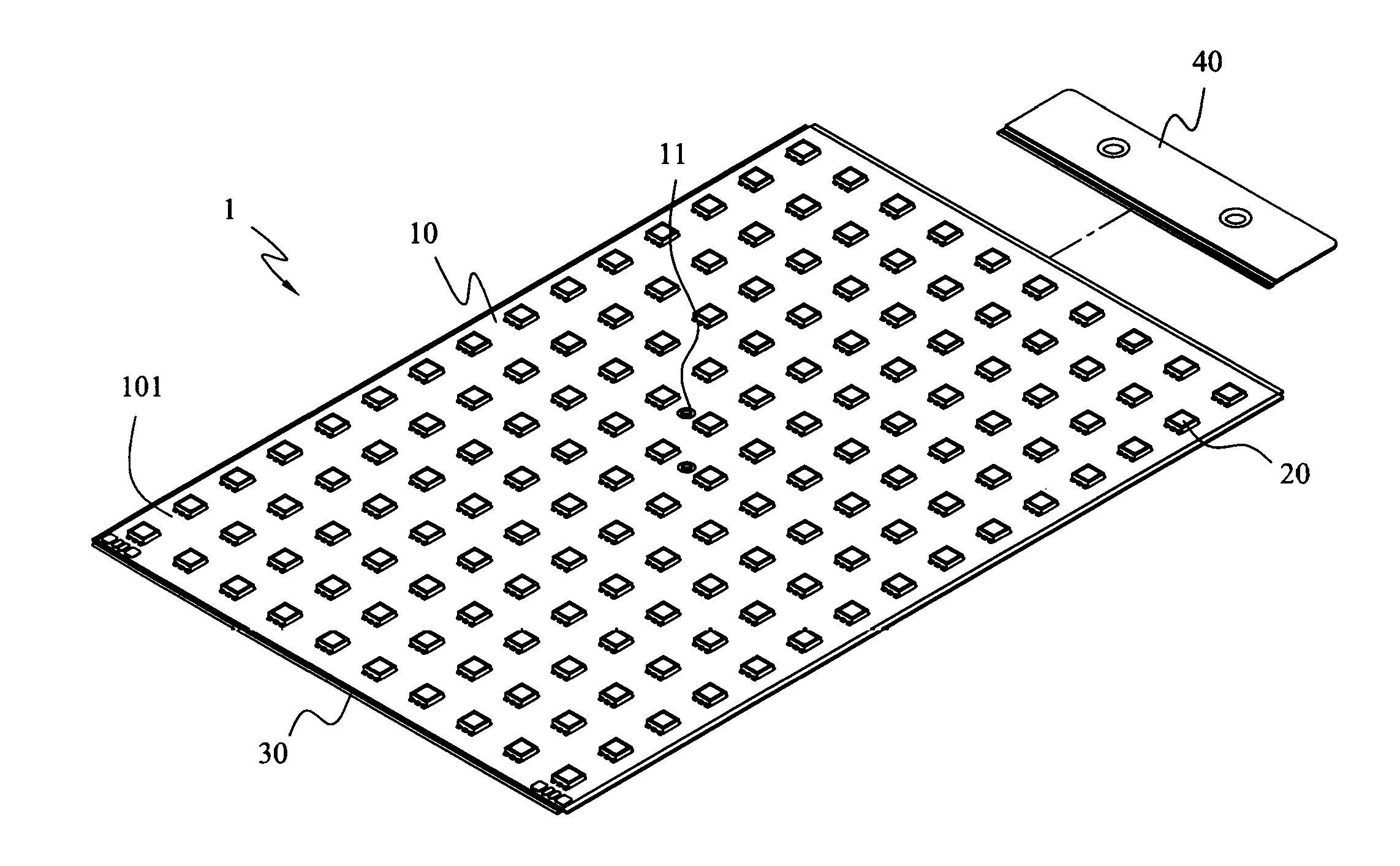
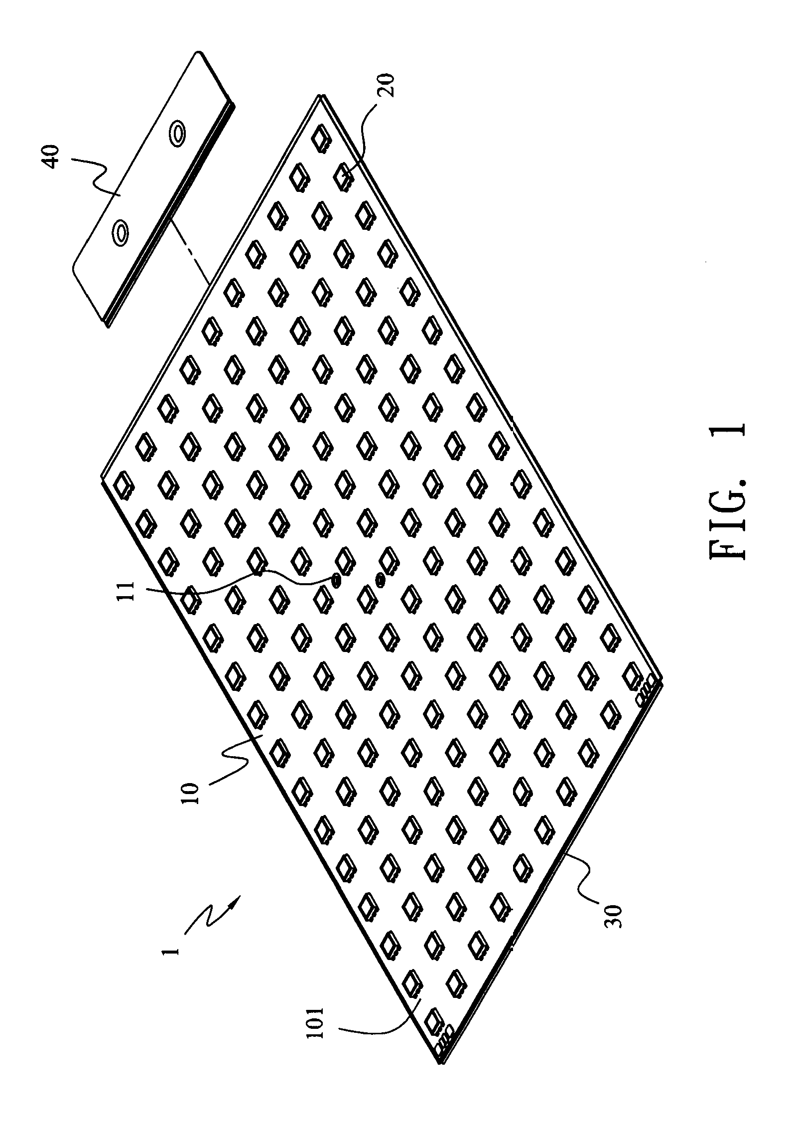
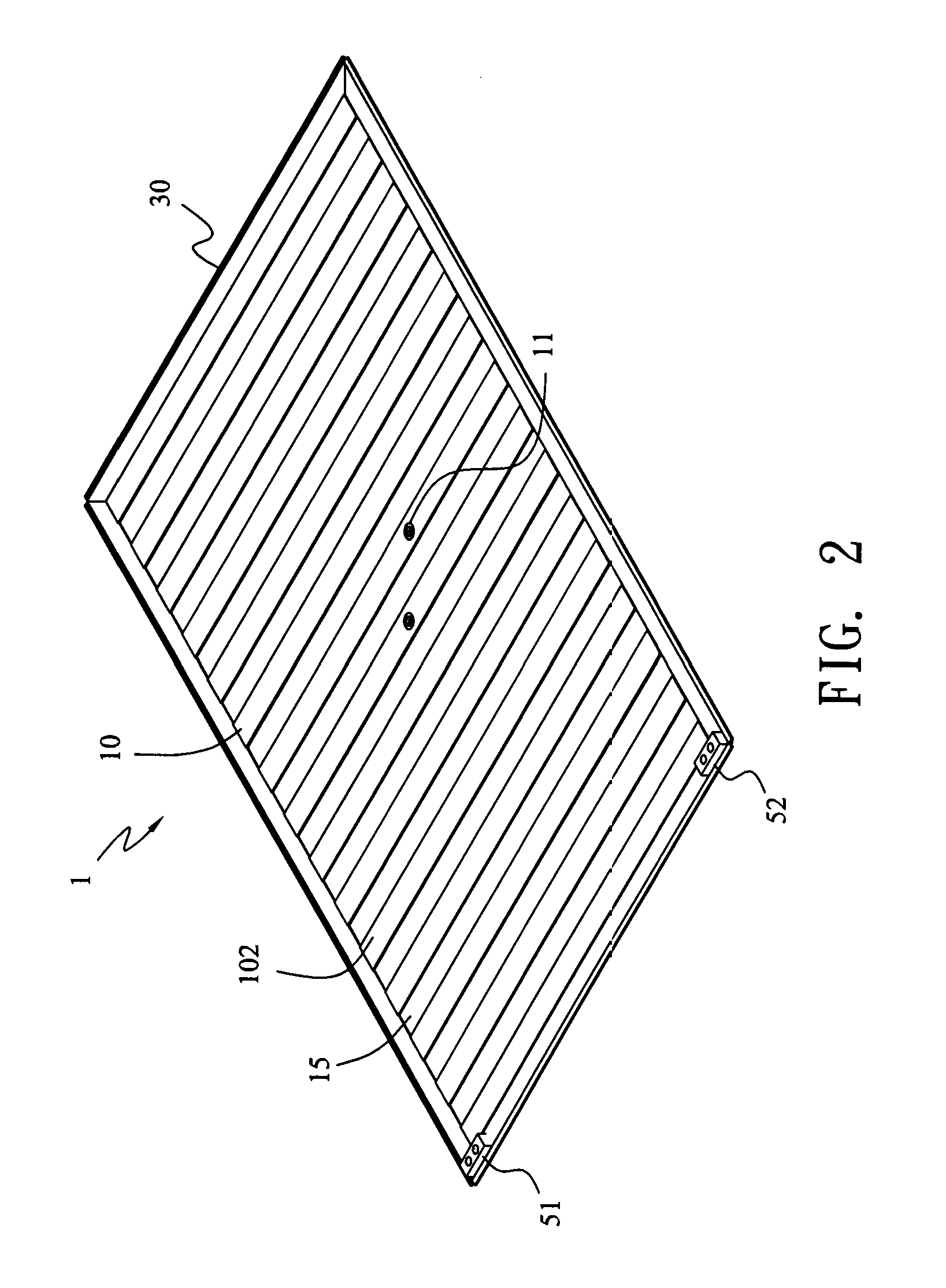
[0021]Please refer to FIG. 1, which is a respective view for the LED module plate of the present invention to show the front side of the LED module plate. Please refer to FIG. 2, which is a schematic view for the LED module plate of the present invention to show the back side of the LED module plate.

[0022]The LED (Light Emitting Diode) display structure having a plurality of LED module plates 1 which can be connected each other, also refer to FIG. 7A. The LED module plates 1 includes a flexible PCB (printed circuit board) 10, a plurality of protective plates 15, a plurality of full-color LED units 20 and connecting edge bandings 30. The flexible PCB 10 includes a first side 101 and a second side 10...


PUM


Abstract

A modular LED (Light Emitting Diode) display structure includes full-color LED units to be arranged in a matrix on a flexible PCB, and plurality of protective plates to protect connection between the full-color LED units and the transmission line of the flexible PCB. Also, the edge of the display has a connecting edge banding with a hook to form a track thereunder. The hook can clip the track of another LED module plate for connection to develop a lager LED display. Moreover, by a hanger connecting to the connecting edge banding to simplify the suspending of the LED display. Furthermore, each full-color LED units has a driving chip to enhance the resolution of the LED display.

Description

BACKGROUND OF THE INVENTION[0001]1. Field of the Invention[0002]The present invention relates to a LED (Light Emitting Diode) display structure, and more particularly, to a LED display structure with a plurality of LED module plate connected each other to develop various sizes of LED display.[0003]2. Related Art[0004]Light plays a significant role for a very long time in human life. Accompanying with the constant progresses of science and technology, LED (Light Emitting Diode) has been invented in 1970s. With the advantages of compact size, long lifetime, low breakage, low power consumption, no heat radiation and no toxic pollution (such as mercury and etc.), comparing with conventional light sources, LED is now broadly utilized in our daily life.[0005]Through the environment / economization policies driven by the governments around the world, LED is well-developed and applied to two major applications including display and illumination functions. Due to plenty of nonstop technology a...

Claims


Application Information

Patent Timeline
Patent Type & Authority Applications(United States)
IPC IPC(8): G09G3/32G06F3/038
CPCG09G3/32H05K1/142H05K1/189G09G2300/0426H05K2201/2009G09G2300/026H05K2201/10106G09F9/3026G09F9/301
Inventor HUANG, HSIEN-JUNG
Owner APA ELECTRONICS
Why Eureka
Try Eureka