Video motion compensation and stabilization gimbaled imaging system

a technology of motion compensation and stabilization, applied in the field of imaging systems, can solve the problems of large size and relative weight of prior art imaging systems, image distortion can occur in images detected, image sensor is generally subject to motion and vibration, etc., and achieves the effect of increasing the dynamic range of the camera, facilitating maintaining an environmental region of interest, and additional degree of freedom

Active Publication Date: 2012-01-26
GOLAN CHEN +1
View PDF1 Cites 67 Cited by
  • Summary
  • Abstract
  • Description
  • Claims
  • Application Information

AI Technical Summary

Benefits of technology

[0031]In variations of the present invention, the camera systems further includes a motorized gimbaled device, wherein the motorized gimbaled device extends the camera dynamic range...

Problems solved by technology

An image sensor is generally subject to motion and vibrations which might distort a detected image of a scene.
Likewise, image distortion can occur in images detected by an image sensor mounted to a ground vehicle, an airborne platform, such as an aircraft, a he...

Method used


Image

  • Video motion compensation and stabilization gimbaled imaging system
  • Video motion compensation and stabilization gimbaled imaging system
  • Video motion compensation and stabilization gimbaled imaging system

Examples


Embodiment Construction

[0041]Before explaining embodiments of the invention in detail, it is to be understood that the invention is not limited in its application to the details of construction and the arrangement of the components set forth in the host description or illustrated in the drawings.

[0042]Unless otherwise defined, all technical and scientific terms used herein have the same meaning as commonly understood by one of ordinary skill in the art of the invention belongs. The methods and examples provided herein are illustrative only and not intended to be limiting.

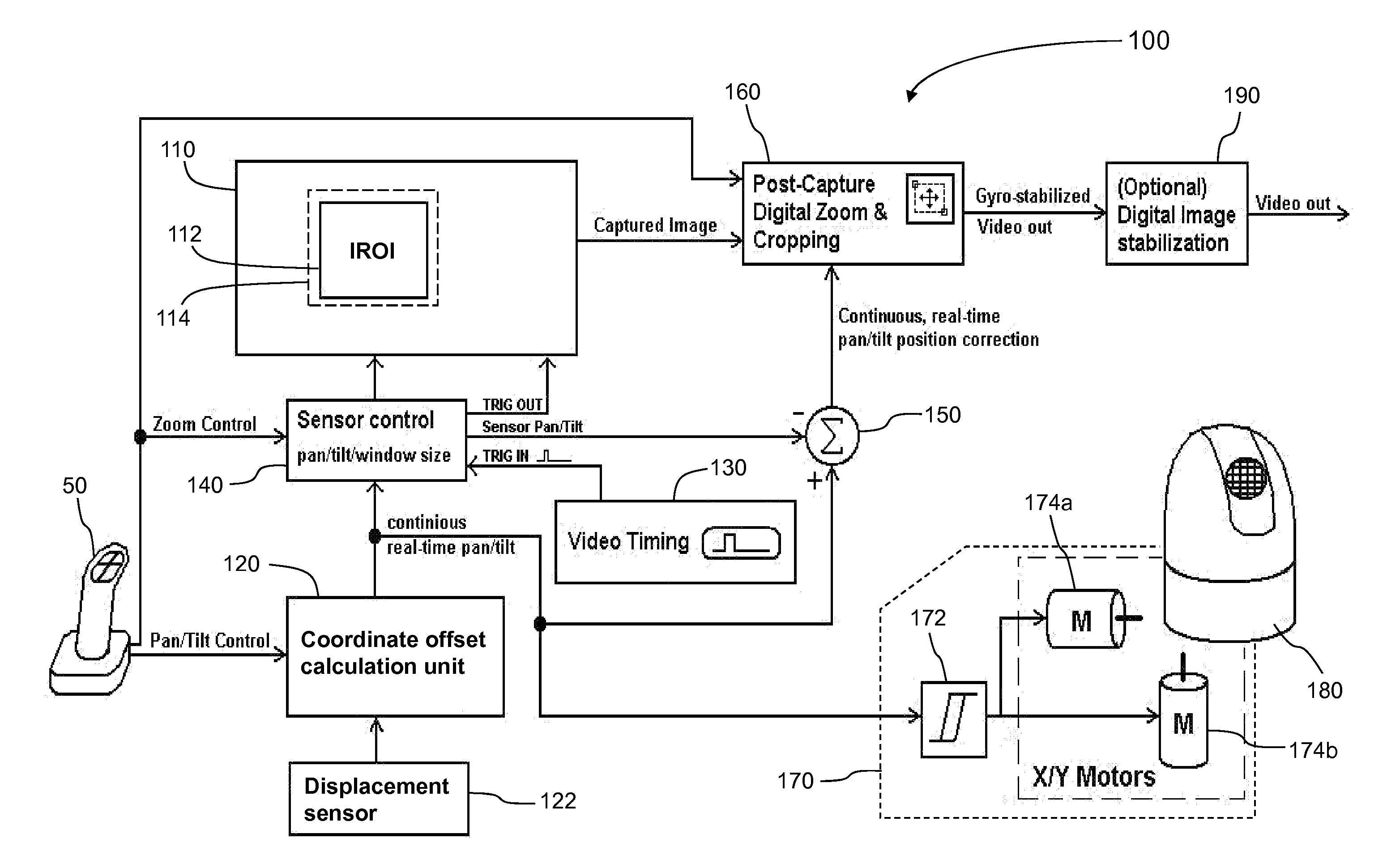
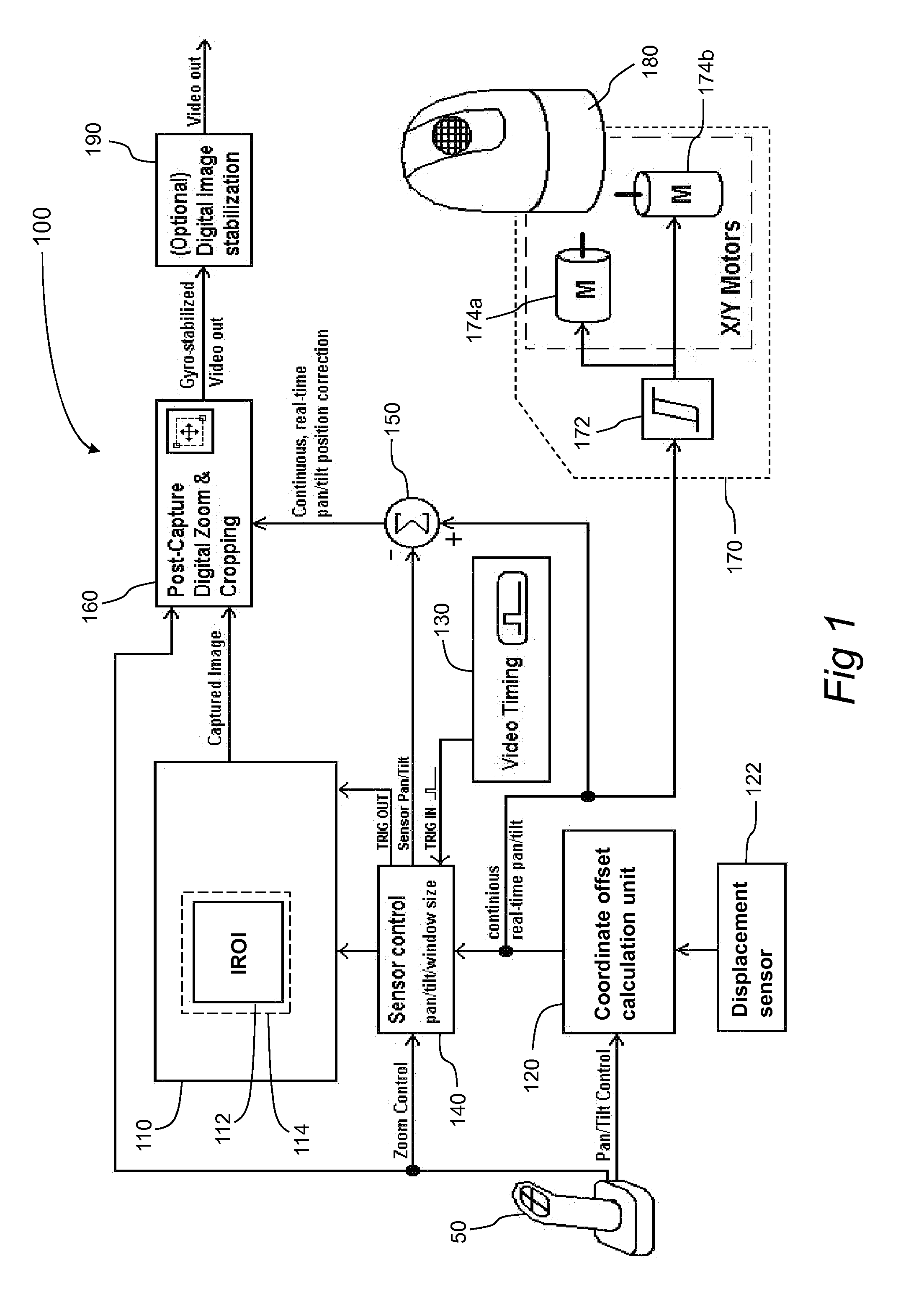
[0043]Reference is now made to the drawings. FIG. 1 is a block diagram illustration of an air-born camera system 100 for performing image acquisition and image transmission, according to the preferred embodiments of the present invention. Air-born camera system 100 includes a high resolution digital image sensor (typically, in current state of the art, higher than 1 mega pixels) 110, a coordinate offset calculation unit 120, a displacemen...


PUM

PropertyMeasurementUnit
Forceaaaaaaaaaa
Distanceaaaaaaaaaa
Hysteresisaaaaaaaaaa

Abstract

A system and method for compensating for image distortions formed by the motion of a computerized camera system mounted on a moving platform. The camera system includes a camera, wherein the camera acquires a plurality of image frames including images of the environment viewed from within the field of view of the camera. The distortion is formed in the acquired image frame, during and in between image acquisitions. During the image acquisition the camera may be maneuvered in space, typically, in the pan and tilt axis. The method includes the steps of providing camera maneuvering signals, providing sensors for detecting other motions of the camera, computing the pre acquisition aggregated motion vector of the camera, thereby determining the pre acquisition image distortion, and compensating for the determined pre acquisition image distortion by an equivalent vector, in a direction opposite to the direction of the pre acquisition aggregated motion vector.

Description

RELATED APPLICATION[0001]The present application claims the benefit of U.S. provisional application 61 / 167,226 filed on Apr. 7, 2009, the disclosure of which is incorporated herein by reference.FIELD OF THE INVENTION[0002]The present invention relates to imaging systems, and more particularly, the present invention relates to an imaging system, operatively mounted on an air-born vehicle, that can transmit high resolution images of a selected region of interest, whereas the images are continuously compensated for vehicle motion.BACKGROUND OF THE INVENTION AND PRIOR ART[0003]An image sensor is generally subject to motion and vibrations which might distort a detected image of a scene. The motion can be linear, where the image sensor undergoes a linear displacement or scaling, and the motion can be angular, where the image sensor rotates about one or more axes. In case of an image sensor mounted on a marine vessel, the image can be distorted as a result of ocean waves. Likewise, image d...

Claims


Application Information

Patent Timeline
IPC IPC(8): H04N7/18
CPCH04N5/232H04N5/23258Y10T29/49826H04N5/2628H04N5/23248H04N5/23264H04N23/682H04N23/6812H04N23/683H04N23/687H04N23/695H04N23/68
Inventor GOLAN, CHENKIPNIS, BORIS
Owner GOLAN CHEN
Why Eureka
Try Eureka