Dispensing Fluid from an Infusion Pump System

a pump system and fluid technology, applied in the field of infusion pump system, can solve the problems of reducing the portability of the user and the size of the device, and achieve the effects of convenient wear, preventable dispensing of medicine, and convenient monitoring of infusion pump operation

Active Publication Date: 2012-01-26
INSULET CORP
View PDF1 Cites 44 Cited by
  • Summary
  • Abstract
  • Description
  • Claims
  • Application Information

AI Technical Summary

Benefits of technology

[0010]Some or all of the embodiments may provide one or more of the following advantages. First, the pump device may be attached to a controller device so that a user can readily monitor infusion pump operation by simply viewing a user interface connected to the pump device. In these circumstances, the user may activate and control the pump device without the requirement of locating and operating a separate monitoring module.
[0011]Second, the infusion pump system may be configured to be portable, wearable, and (in some circumstances) concealable. For example, a user can conveniently wear the infusion pump system on the user's skin under clothing or can carry the pump device in the user's pocket (or other portable location) while receiving the medicine dispensed from the pump device.
[0012]Third, a number of preparatory functions can be accomplished while the user performs the relatively simple task of attaching the cap device to the pump housing. For example, attachment of the cap device can cause the medicine cartridge to be retained in a cavity of the pump housing and can provide a water-tight seal f

Problems solved by technology

One such factor is the size of the device.
The pump device may be sized to house the

Method used


Image

  • Dispensing Fluid from an Infusion Pump System
  • Dispensing Fluid from an Infusion Pump System
  • Dispensing Fluid from an Infusion Pump System

Examples


Embodiment Construction

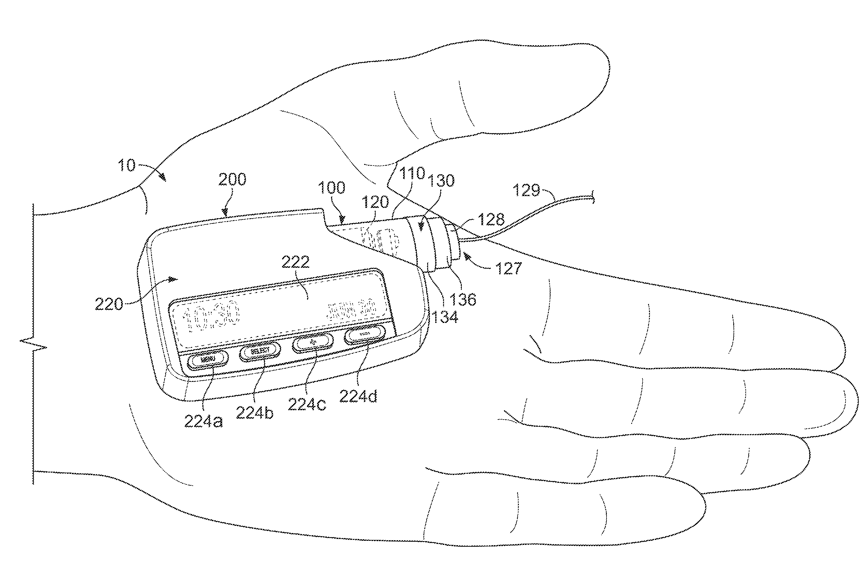
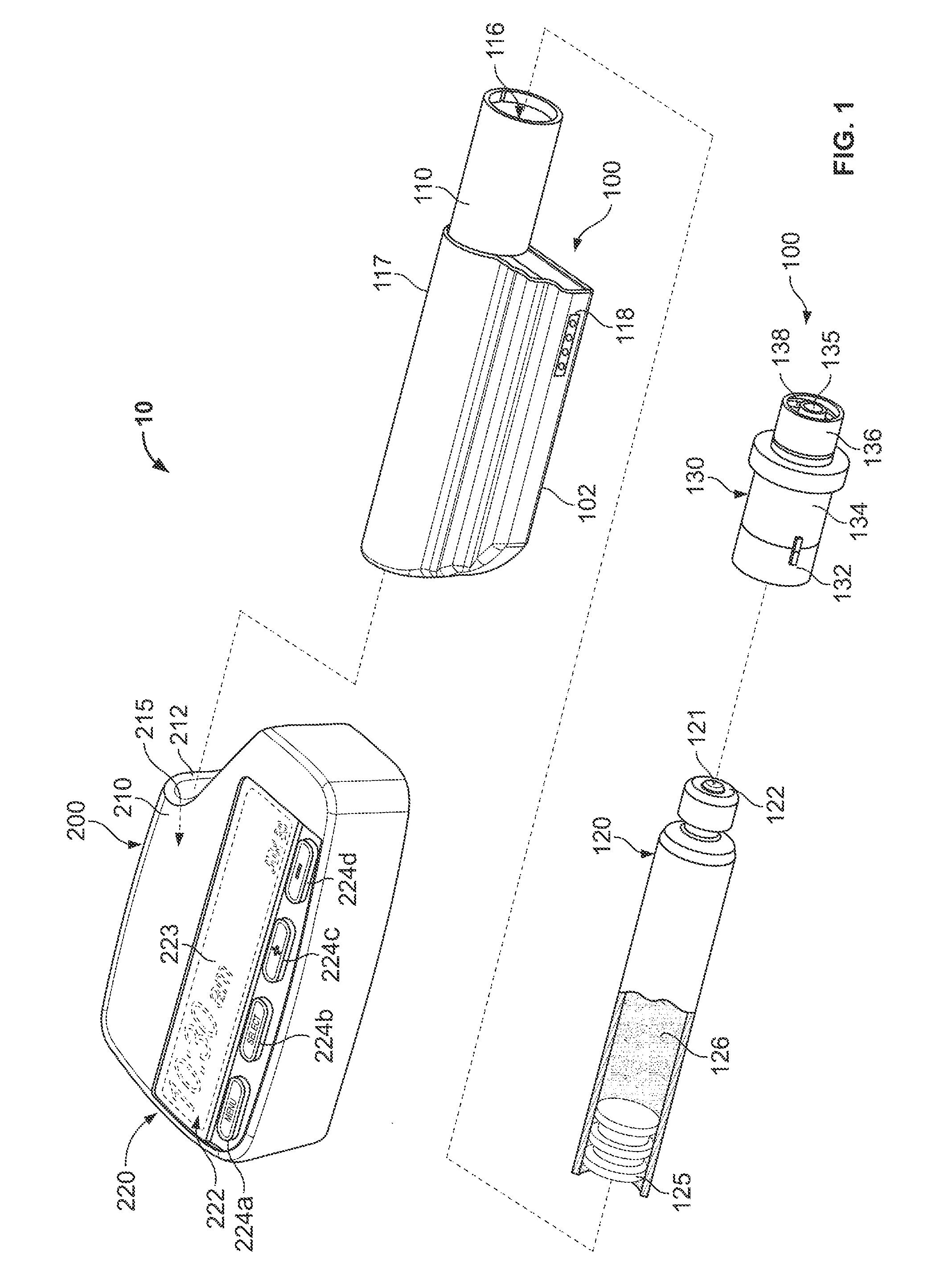
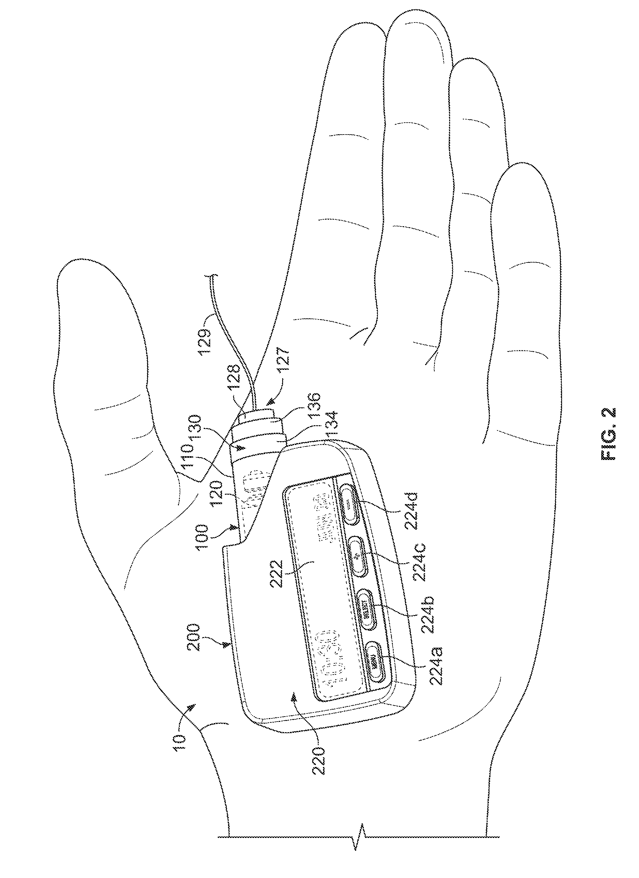
[0048]Referring to FIG. 1, an infusion pump system 10 can include a pump device 100 and a controller device 200 that communicates with the pump device 100. The pump device 100 includes a housing structure 110 that defines a cavity 116 in which a fluid cartridge 120 can be received. The pump device 100 also includes a cap device 130 to retain the fluid cartridge 120 in the cavity 116 of the housing structure 110. The pump device 100 includes a drive system (described in more detail below) that advances a plunger 125 in the fluid cartridge 120 so as to dispense fluid therefrom. The controller device 200 communicates with the pump device 100 to control the operation of the drive system. When the controller device 200, the pump device 100 (including the cap device 130), and the fluid cartridge 120 are assembled together, the user can (in some embodiments) conveniently wear the infusion pump system 10 on the user's skin under clothing or in the user's pocket while receiving the fluid dis...


PUM


Abstract

Some embodiments of a medical infusion pump system include a pump device having a cap device that mates with a pump housing to retain a medicine cartridge therein. In addition to retaining the medicine cartridge in the pump housing, the cap device may perform a number of preparatory functions or safety functions. In addition or in the alternative, some embodiments of the pump device may include a drive system that advances a piston rod to dispense medicine to the patient in a safe and energy efficient manner.

Description

CROSS-REFERENCE TO RELATED APPLICATIONS[0001]This application is a division of U.S. patent application Ser. No. 11 / 677,706 filed on Feb. 22, 2007, which is a continuation-in-part of: (1) U.S. patent application Ser. No. 11 / 522,603 filed on Sep. 18, 2006, (2) U.S. patent application Ser. No. 11 / 522,560 filed on Sep. 18, 2006, and (3) U.S. patent application Ser. No. 11 / 522,836 filed on Sep. 18, 2006. The contents of these prior applications are fully incorporated by reference herein.TECHNICAL FIELD[0002]This document relates to an infusion pump system, such as a medical infusion pump system.BACKGROUND[0003]Pump devices are commonly used to deliver one or more fluids to a targeted individual. For example, a medical infusion pump device may be used to deliver a medicine to a patient as part of a medical treatment. The medicine that is delivered by the infusion pump device can depend on the condition of the patient and the desired treatment plan. For example, infusion pump devices have ...

Claims


Application Information

Patent Timeline
IPC IPC(8): A61M5/142
CPCA61M5/1452A61M5/14244
Inventor CAUSEY, JAMESKIRSCHEN, TODDWENGER, MITCHELLFRIEDMAN, STEVENCOLTON, JOSHUACHRISTENSEN, KELD SLOTH
Owner INSULET CORP
Why Eureka
Try Eureka