Control device for vehicle power transmission device

a technology of power transmission device and control device, which is applied in the direction of engine-driven generators, propulsion parts, process and machine control, etc., can solve problems such as problematic degradation of the efficiency of an entire power transmission device, reduce the regenerative torque of the second electric motor, and suppress the increase in the size of the shifting portion

Inactive Publication Date: 2012-01-26
TOYOTA JIDOSHA KK
View PDF18 Cites 45 Cited by
  • Summary
  • Abstract
  • Description
  • Claims
  • Application Information

AI Technical Summary

Benefits of technology

[0006]The present invention was conceived in view of the situations and it is therefore an object of the present invention to provide a control device for a vehicle power transmission device capable of improving fuel economy by providing control in consideration of efficiency of an entire vehicle power transmission device when regenerative control is provided.
[0019]More preferably, the shifting portion is a mechanical stepped transmission. Accordingly, the shifting portion is a stepped transmission capable of varying the gear ratio in a stepped manner and, therefore, in addition to the above-indicated effect, when an amount of change is increased in the gear ratio of the shifting portion, an increase in size of the shifting portion can be suppressed.

Problems solved by technology

Since efficiency of a transmission and a loss in an electric motor vary depending on temperature, even if a downshift of a transmission is executed to increase the rotation speed of the electric motor and improve the energy regenerative efficiency when the regenerative control is provided as described in Patent Document 1, efficiency of an entire power transmission device may problematically deteriorate due to increase in the loss in the electric motor or deterioration in the efficiency of the transmission.

Method used


Image

  • Control device for vehicle power transmission device
  • Control device for vehicle power transmission device
  • Control device for vehicle power transmission device

Examples


first embodiment

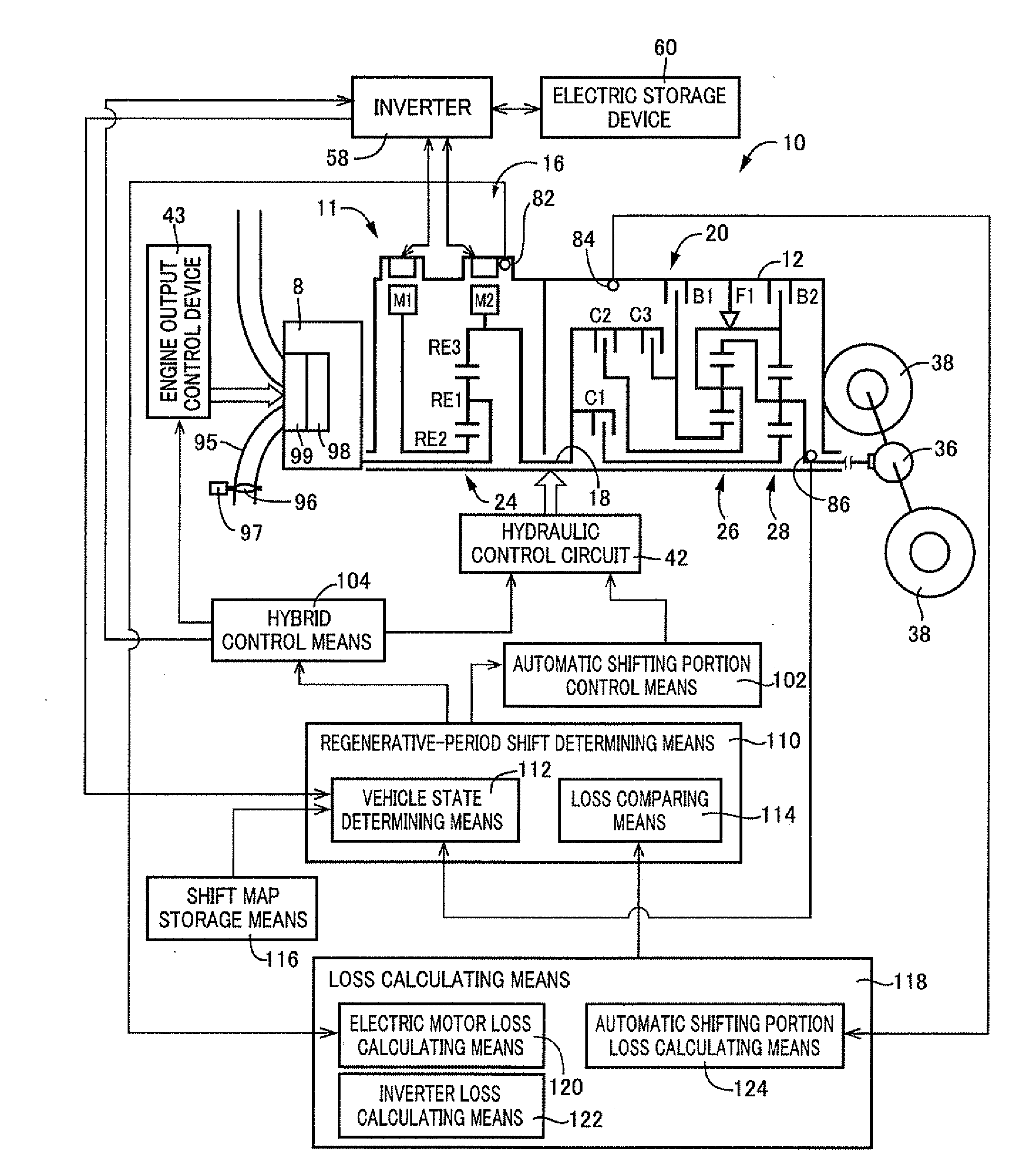
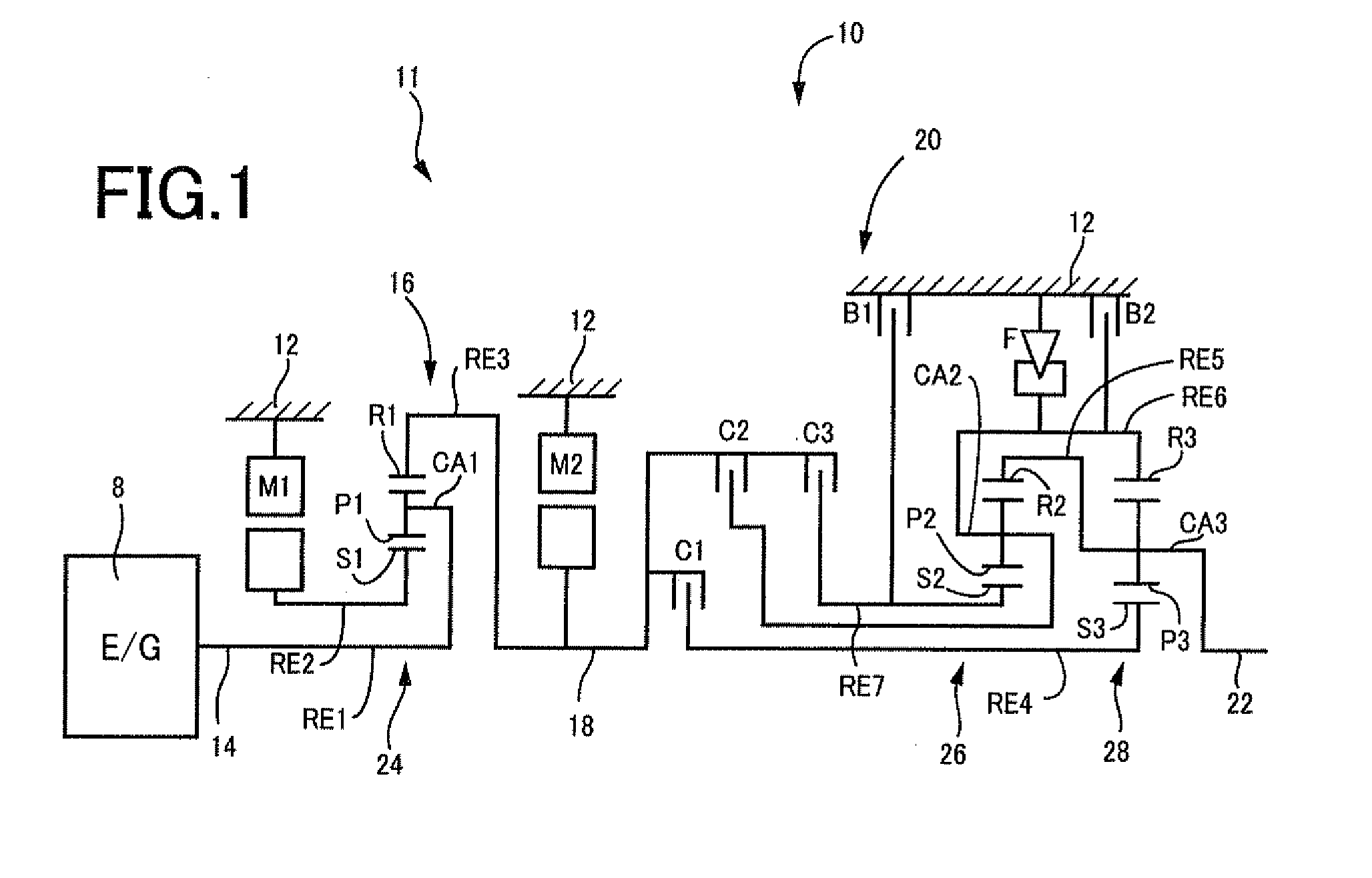
[0055]FIG. 1 is a schematic for explaining a vehicle power transmission device (hereinafter, simply the “power transmission device”) 10 making up a portion of a drive device of a hybrid vehicle to which the present invention is applied. In FIG. 1, the power transmission device 10 includes, in series, an input shaft 14 as an input rotating member disposed on a common shaft center in a transmission case 12 (hereinafter, the case 12) that is a non-rotating member attached to a vehicle body; a differential portion 11 as a stepless shifting portion coupled to the input shaft 14 directly or indirectly via a pulsation absorbing damper (pulsation damping device) not depicted; an automatic shifting portion 20 as a power transmitting portion serially coupled via a transmitting member 18 on a power transmission path from the differential portion 11 to drive wheels 38 (see FIG. 6); and an output shaft 22 as an output rotating member coupled to the automatic shifting portion 20. The power transm...

second embodiment

[0127]In this embodiment, the regenerative-period shift determining means 110 functionally includes a vehicle state determining means 112. The vehicle state determining means 112 makes a determination on a shift of the automatic shifting portion 20 by applying a vehicle state, for example, a vehicle speed v and an output power or an output torque of the second electric motor M2 providing the regenerative control, to a regenerative traveling shift map stored in advance in a shift map storage means 116 described later.

[0128]The shift map storage means 116 preliminarily stores the regenerative traveling shift map, i.e., a relationship for determined whether a downshift of the automatic shifting portion 20 is executed when a vehicle travels in a regenerative manner. This relationship uses, for example, the vehicle speed v and the output power of the second electric motor M2 providing the regenerative control, or the vehicle speed v and the output torque of the second electric motor M2 p...


PUM


Abstract

It is provided a control device for a vehicle power transmission device including a shifting portion and an electric motor that provides regeneration via the shifting portion, the control device executing a downshift of the shifting portion if a traveling loss in the vehicle power transmission device after the shift is smaller than a traveling loss in the vehicle power transmission device at a current gear ratio during regenerative traveling, and the traveling loss in the vehicle power transmission device including at least one of a loss in the shifting portion and a loss in the electric motor, the loss in the shifting portion being calculated based on the operating oil temperature of the shifting portion and the loss in the electric motor being calculated based on the temperature of the electric motor.

Description

TECHNICAL FIELD[0001]The present invention relates to a control device for a vehicle power transmission device and particularly to a technique for enabling a gear shifting in consideration of a loss in a shifting mechanism, etc., making up the vehicle power transmission device during regenerative traveling.BACKGROUND ART[0002]A so-called hybrid car is known that includes a plurality of power sources. For example, Patent Document 1 discloses a hybrid car including an engine and an electric motor (motor generator). Such a hybrid car can provide so-called regenerative control that converts a kinetic energy of a vehicle with the electric motor into an electric energy to be accumulated during deceleration of the vehicle.[0003]Patent Document 1 discloses a technique for increasing the rotation speed of the electric motor by executing a downshift of a transmission for the purpose of improving the energy regenerative efficiency if the regenerative control is provided when a deceleration req...

Claims


Application Information

Patent Timeline
Patent Type & Authority Applications(United States)
IPC IPC(8): F16H61/02B60L50/15B60L50/16B60W10/10B60W30/18
CPCB60K1/02Y02T10/7258B60K6/445B60K6/547B60L7/14B60L11/123B60L11/14B60L2240/36B60L2240/421B60L2240/423B60L2240/425B60L2240/485B60W10/08B60W10/115B60W20/00B60W30/18127B60W2510/087B60W2510/107F16H59/72F16H61/0213F16H2003/445F16H2037/0866F16H2200/0043F16H2200/2007F16H2200/2043Y02T10/56Y02T10/6217Y02T10/6239Y02T10/642Y02T10/7077B60K6/365Y02T10/84B60L50/61B60L50/16Y02T10/40Y02T10/62Y02T10/64Y02T10/72Y02T10/7072Y02T10/70B60K23/00B60W20/30
Inventor KUMAZAKI, KENTAMATSUBARA, TOORUTABATA, ATSUSHI
Owner TOYOTA JIDOSHA KK
Why Eureka
Try Eureka