
Method for Gasification and A Gasifier

a gasification and gasifier technology, applied in the direction of combustible gas production, lighting and heating apparatus, combustion types, etc., can solve the problems of reducing and reducing the operation of known cyclonic reactors. , to achieve the effect of reducing or eliminating operational shutdowns, reducing wall refractory erosion, and extending the life of refractory materials

Inactive Publication Date: 2012-02-02
AIR PROD & CHEM INC
View PDF2 Cites 18 Cited by
  • Summary
  • Abstract
  • Description
  • Claims
  • Application Information

AI Technical Summary

Benefits of technology

[0013]An advantage of the present disclosure includes control of slag temperature and viscosity, which can reduce or eliminate operational shutdowns due to slag cooling and thickening.
[0014]Another advantage of the present disclosure includes introducing solid fuel with a low angle of attack relative to the reactor wall, thereby reducing wall refractory erosion and extending the life of refractory material.
[0015]Another advantage of the present disclosure includes maintaining cyclonic action while using an oxidizer with a low concentration of inert gas, thereby reducing the adverse effects of inert gas on gasification processes.

Problems solved by technology

Generally, operation of known cyclonic reactors can present drawbacks.
Due to temperature gradients within a cyclonic reactor, there is a tendency for slag to solidify within the reactor, most particularly in the region near where the slag exits the reactor.
Heat loss from the slag near the slag tap may be relatively high due to the large thermal gradient between the reactor and the quench tank.
High heat loss sharply increases the viscosity of the slag, thereby decreasing the flow rate of the slag and often leads to solidification of the slag.
This process of slag cooling, viscosity increase, and solidification can lead to a decrease in thermal efficiency for the reactor, an increase in particulate emissions, and / or operational shutdown.
The replacement of the portions of the refractor wall results in material costs for the replacement material, operational costs for handling the replacement of the refractory material, and an inability to use the reactor during the replacement of the refractory material.
The effectiveness of certain processes and the range of chemical interaction capable is limited by the volume of the reactor.
Thus, slow burning fuel feedstocks, such as those with high moisture level (for example, exceeding about 15% by weight) or large particle size (for example, having a dimension of about ¼ inch), may not be oxidized to a desirable degree, resulting in reduced fuel utilization and / or reduced efficiency for combustion and / or gasification.
In addition, this system requires a separator wall exposed to relatively high temperatures on both sides (for example, above about 1400° C.) without a heat sink, thereby risking high temperature failure of this element.
This system can also result in erosion of the reactor wall caused by a high power / velocity plasma jet directed between about 20 and 40 degrees above the plane of the surface of impingement.
This method does not include a secondary fuel within the cyclonic reactor and can result in erosion of the reactor wall due to high velocity injection.
Additionally, this method can also be prone to refractory erosion.

Method used


Image

  • Method for Gasification and A Gasifier
  • Method for Gasification and A Gasifier
  • Method for Gasification and A Gasifier

Examples


Embodiment Construction

[0031]Provided is a method of gasification and a gasifier involving cyclonic gasification. Embodiments maintain the temperature and viscosity of slag within the gasifier, substantially protect the gasifier from erosion, utilize oxidant(s) having little or no inert gas, retain gas momentum for gasification, include compact arrangement with a high heat release to volume ratio, rapidly heat and ignite solid fuel particles, and / or extend residence time and uniformity of temperature distribution.

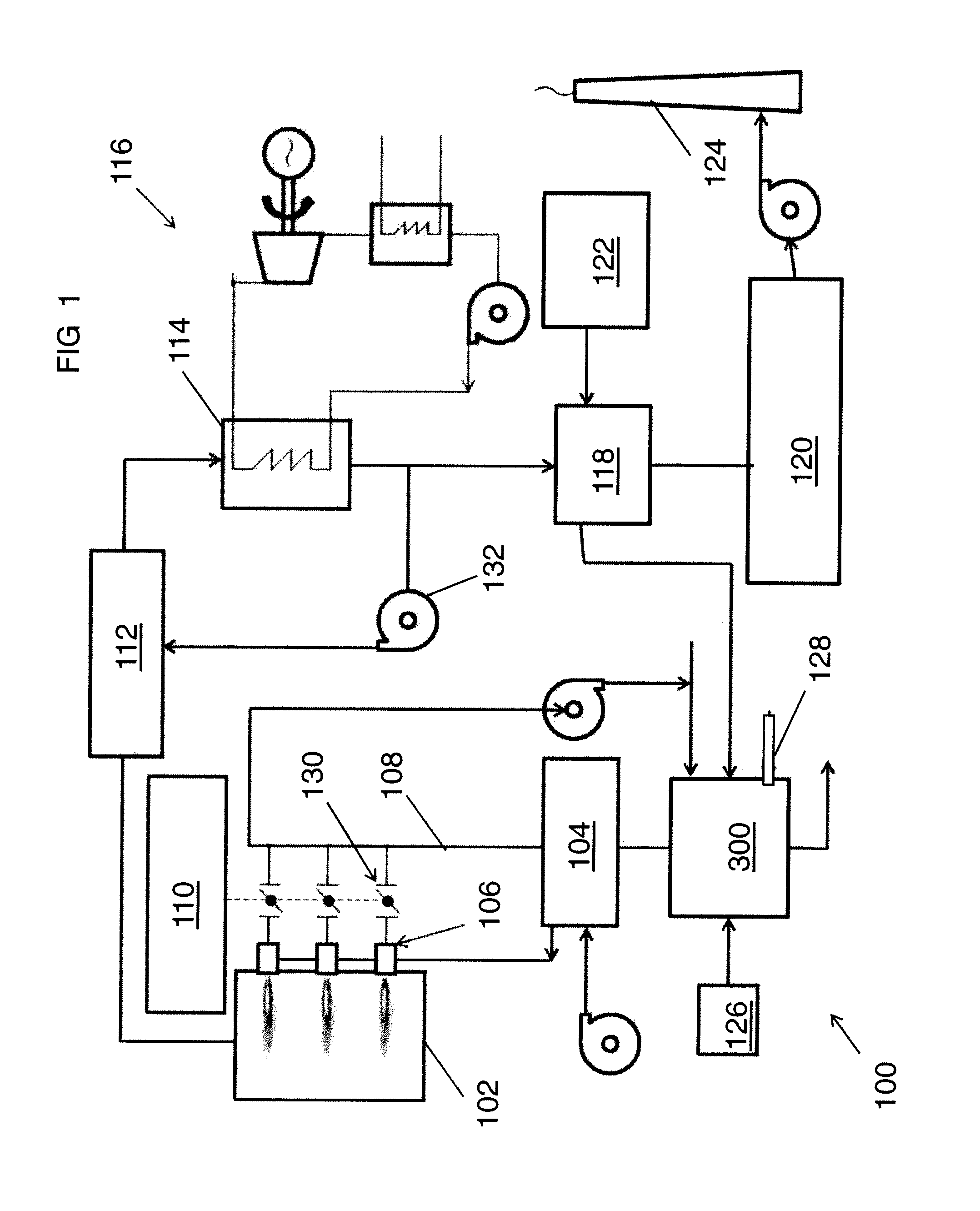
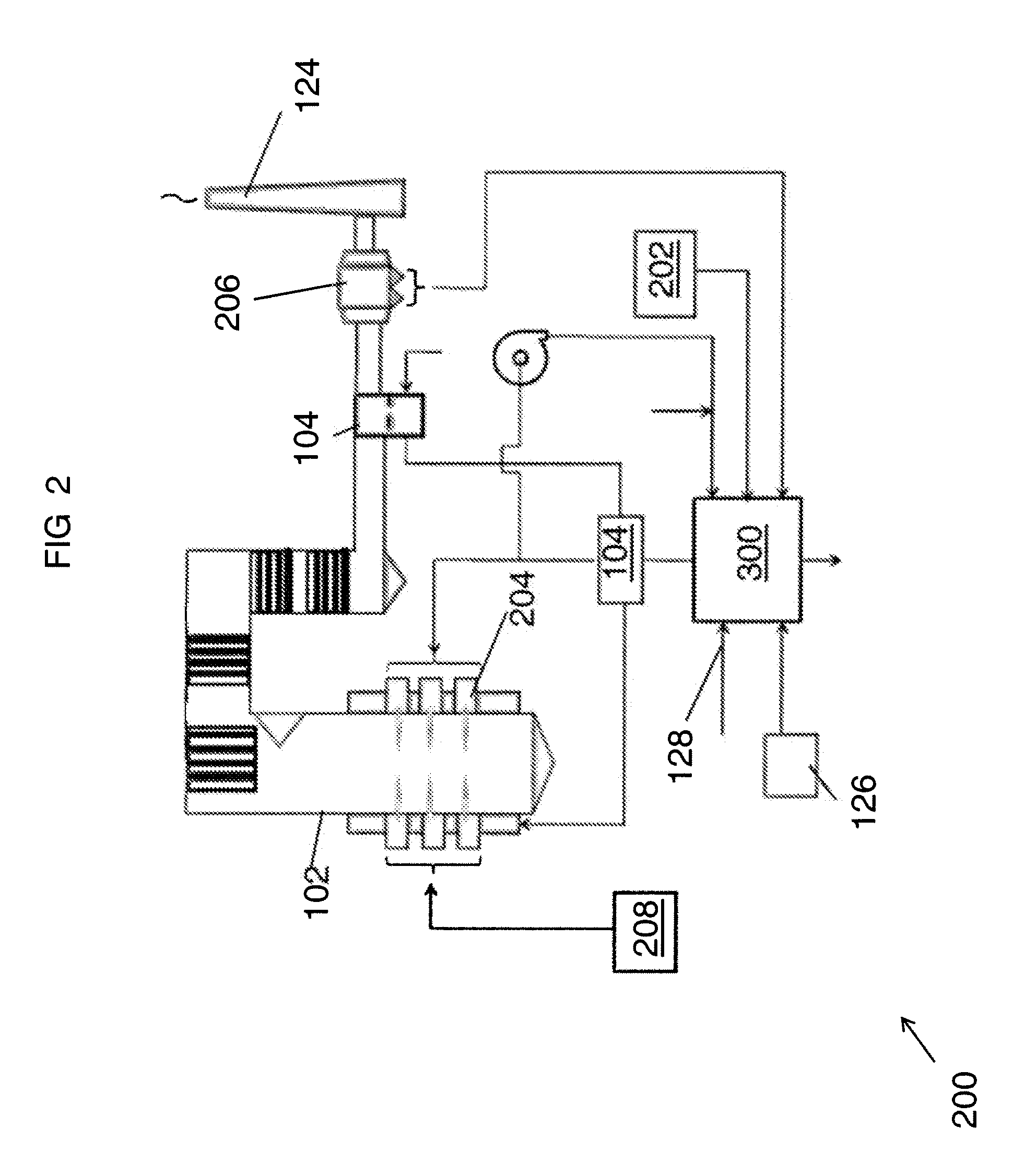
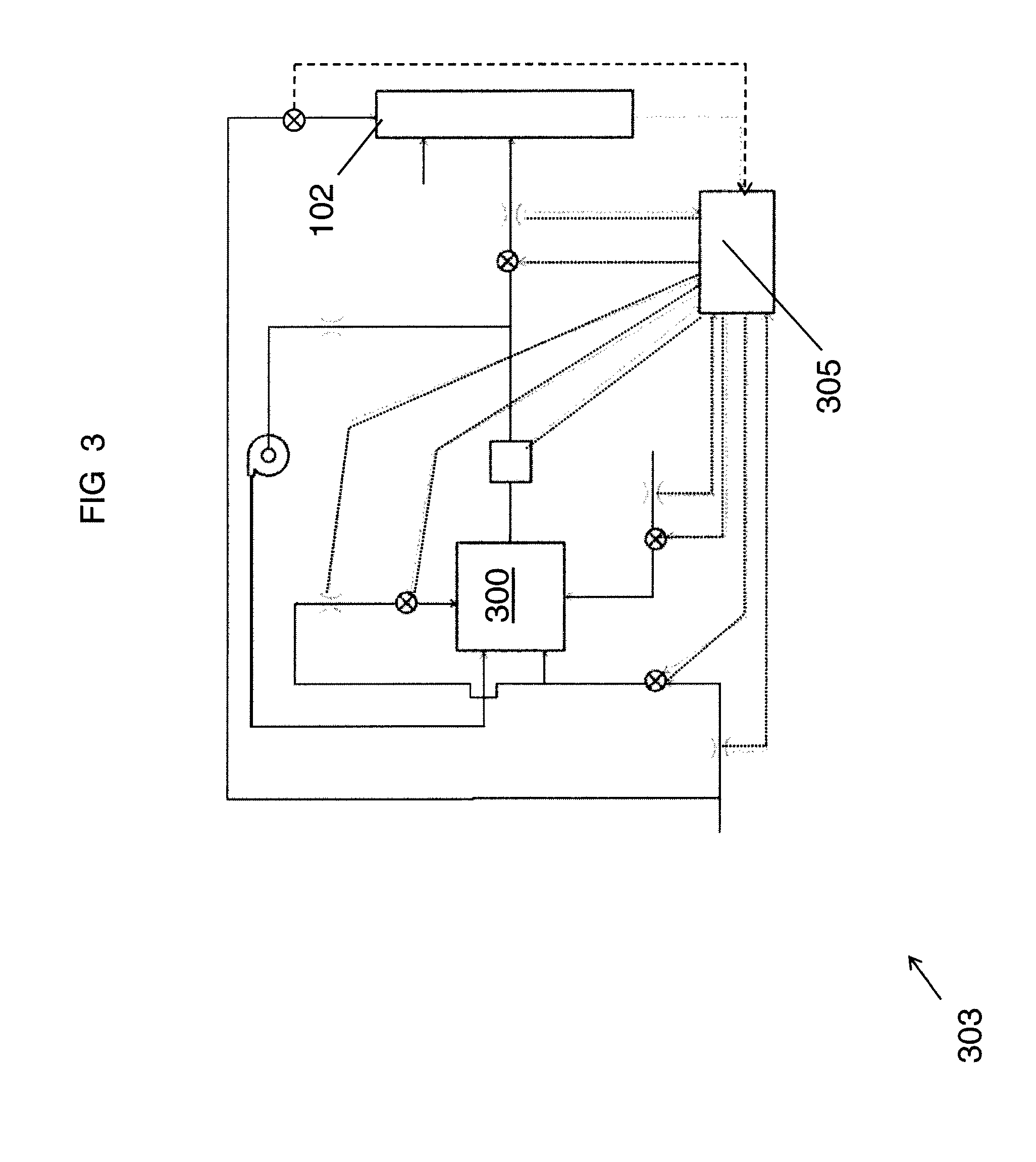
[0032]FIGS. 1, 2, and 3 show exemplary systems including an exemplary cyclone gasifier 300. FIGS. 4 through 13 show various views and / or embodiments of the gasifier 300. Suitable systems include, but are not limited to, energy-intensive systems (such as for pulp and paper, glass, steel, non-ferrous, utilities, biorefining) and systems retaining captive biomass feedstock or organic by-products (such as for forestry, pulp and paper, food processing—animal and vegetable, agriculture and biorefining)...


PUM

PropertyMeasurementUnit
velocityaaaaaaaaaa
velocityaaaaaaaaaa
contact angleaaaaaaaaaa

Abstract

Disclosed is a cyclonic gasifier and cyclonic gasification method. The cyclonic gasifier and cyclonic gasification method involve a chamber having a first portion proximal to a first end and a second portion proximal to a second end, introducing a first fuel to the first portion of the chamber, introducing a second fuel to the chamber; and introducing a first oxidant to accelerate the velocity of the first fuel and swirl the first fuel from the first portion toward the second portion.

Description

BACKGROUND OF THE INVENTION[0001]The present invention is directed to a method of gasification and a gasifier. More specifically, the present invention relates to a method of gasification and a gasifier involving cyclonic gasification.[0002]Generally, operation of known cyclonic reactors can present drawbacks. Due to temperature gradients within a cyclonic reactor, there is a tendency for slag to solidify within the reactor, most particularly in the region near where the slag exits the reactor. For example, in known cyclonic reactors, the slag travels through the slag tap and the slag transfers heat by radiation to a cooler environment such as a quench tank. Heat loss from the slag near the slag tap may be relatively high due to the large thermal gradient between the reactor and the quench tank. High heat loss sharply increases the viscosity of the slag, thereby decreasing the flow rate of the slag and often leads to solidification of the slag. This process of slag cooling, viscosit...

Claims


Application Information

Patent Timeline
Patent Type & Authority Applications(United States)
IPC IPC(8): C10J3/46C10J3/72
CPCF23G5/12F23G2203/30F23G5/32C10B53/00C10J3/72F23C10/08F23G5/027
Inventor D'AGOSTINI, MARK DANIEL
Owner AIR PROD & CHEM INC
Learn More