System and method for direction drilling

a directional drilling and system technology, applied in the direction of directional drilling, borehole/well accessories, survey, etc., can solve the problems of inaccurate estimated location and/or estimated position of the drill bit, the drill bit's trajectory deviating from the trajectory, and the rss is typically more expensive to operate than a mud motor system

Inactive Publication Date: 2012-02-02
SCHLUMBERGER TECH CORP
View PDF10 Cites 102 Cited by
  • Summary
  • Abstract
  • Description
  • Claims
  • Application Information

AI Technical Summary

Problems solved by technology

Typically, the trajectory of the drill bit deviates from the trajectory established by the well plan because of unpredicted characteristics of the formations being penetrated and / or the varying forces that the drill bit and the drill string experience.
A RSS is typically more expensive to operate than a mud motor system.
The D&I measurements at this distance from the BHA may not be indicative of the actual D&I at the drill bit, and, accordingly, the estimated location and / or the estimated position of the drill bit may be inaccurate.
The directional drilling may be compromised because of the inaccurate estimated location of the drill bit.
In addition, moving the drill bit to the drilling path established by the well plan may be difficult after deviation from the drilling path.

Method used


Image

  • System and method for direction drilling
  • System and method for direction drilling
  • System and method for direction drilling

Examples


Embodiment Construction

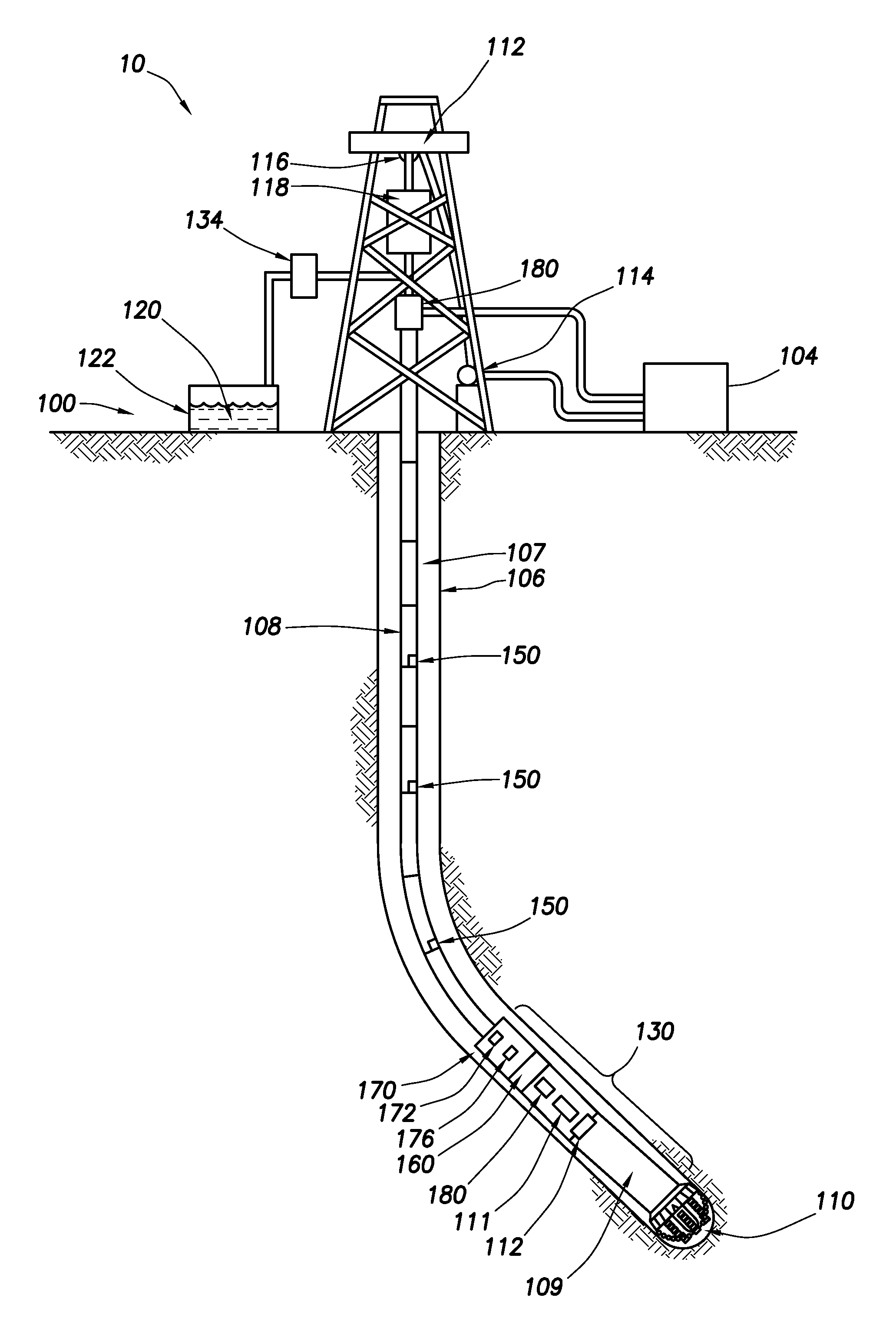
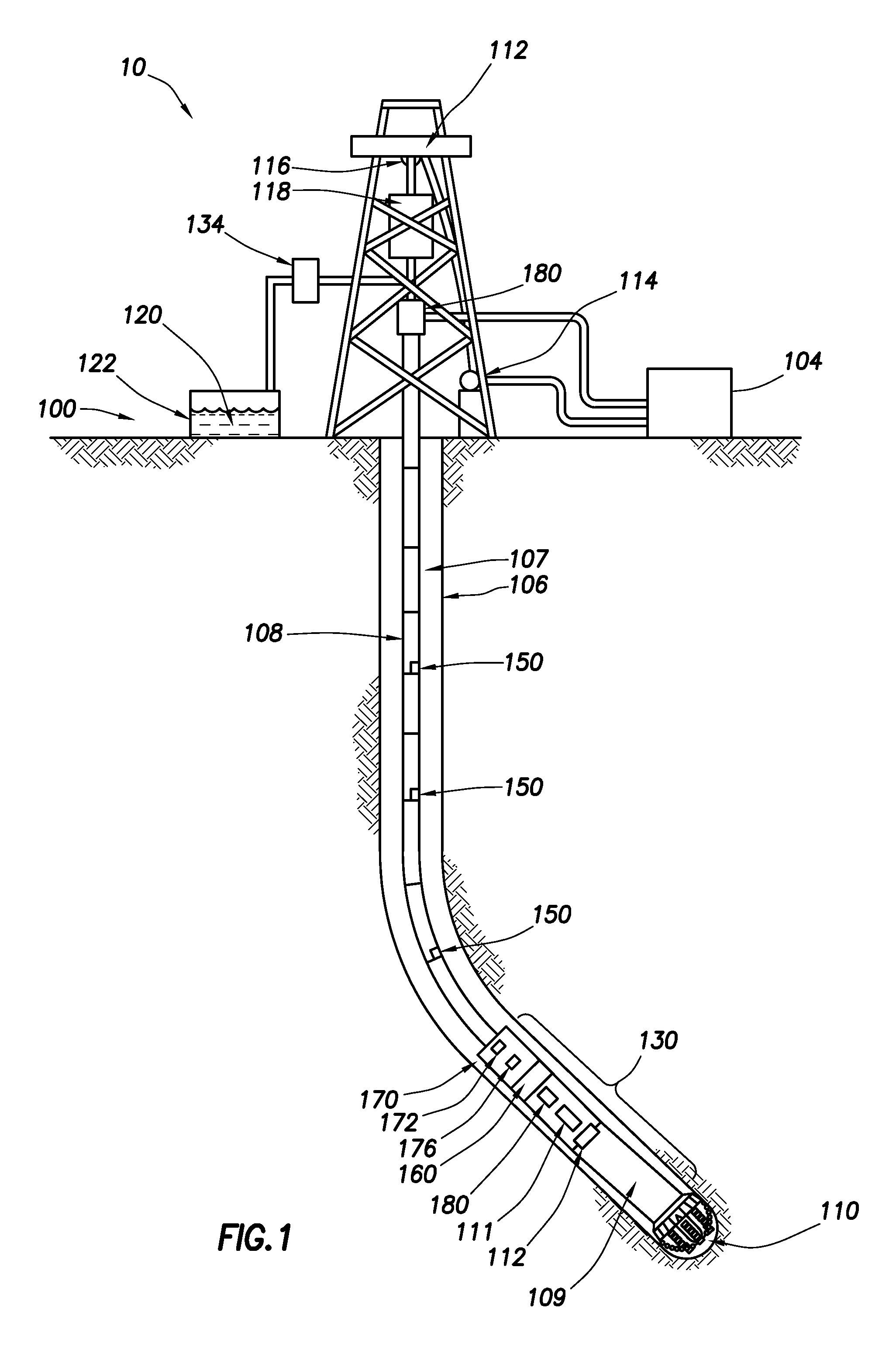
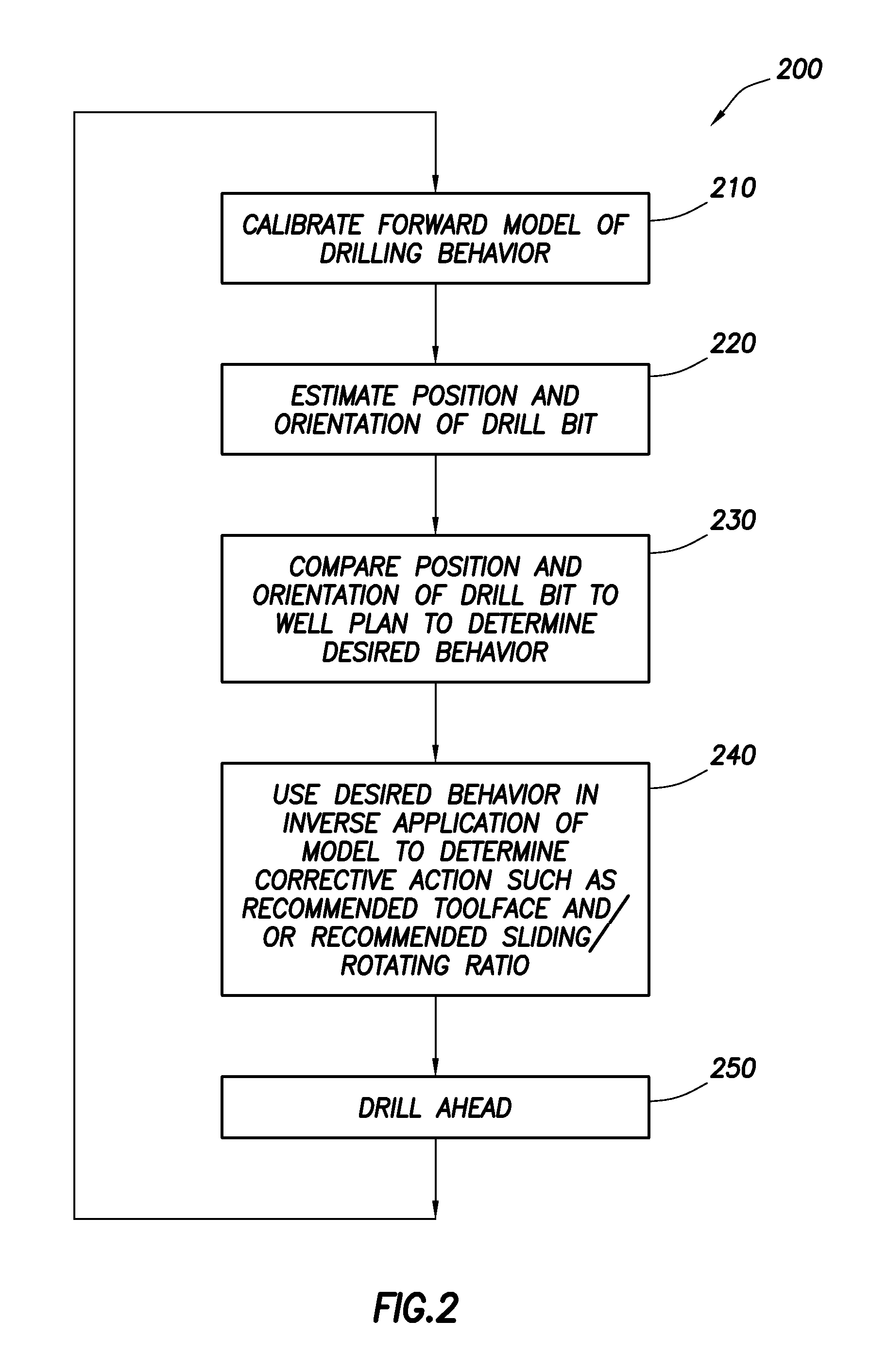
[0014]The present disclosure generally relates to a system and a method for directional drilling. More specifically, the present disclosure relates to a system and a method which may estimate a position and an orientation of the drill bit during directional drilling and / or may determine intervals of sliding and rotating to conform the directional drilling to a well plan.

[0015]Referring now to the drawings wherein like numerals refer to like parts, FIG. 1 generally illustrates a directional drilling system 10 (hereinafter “the system 10”). A drilling operation may be conducted at a wellsite 100 using the directional drilling system. The wellsite 100 may have a wellbore 106 formed by drilling and / or penetrating one or more subsurface formations.

[0016]The system 10 may have a terminal 104. The terminal 104 may be, for example, a desktop computer, a laptop computer, a mobile cellular telephone, a personal digital assistant (“PDA”), a 4G mobile device, a 3G mobile device, a 2.5G mobile d...


PUM


Abstract

A system and a method for directional drilling may generate a model of steering behavior which may be used to estimate a position and an orientation of the drill bit during directional drilling. The estimated position and the estimated orientation may be compared to the well plan to determine desired drilling behavior, and the desired drilling behavior may be used to determine a recommended toolface orientation and / or recommended intervals of sliding and rotating to conform the directional drilling to the well plan.

Description

BACKGROUND[0001]The present disclosure generally relates to a system and a method for directional drilling. More specifically, the present disclosure relates to a system and a method which may estimate a position and an orientation of the drill bit during directional drilling.[0002]To obtain hydrocarbons, a drill bit is driven into the ground surface to create a wellbore through which the hydrocarbons are extracted. Typically, a drill string is suspended within the wellbore, and the drill bit is located at a lower end of sections of drill pipe which form the drill string. The drill string extends from the surface to the drill bit. The drill string has a bottom hole assembly (“BHA”) located proximate to the drill bit.[0003]Directional drilling is the steering of the drill bit so that the drill string travels in a desired direction. Before drilling begins, a well plan is established which indicates a target location and a drilling path to the target location. After drilling commences,...

Claims


Application Information

Patent Timeline
Patent Type & Authority Applications(United States)
IPC IPC(8): E21B7/04G06G7/48
CPCE21B7/04G01C21/16E21B47/024E21B44/00E21B44/005
Inventor PIROVOLOU, DIMITRIOSZAMANIAN, SAM AHMADSANCHEZ, HECTOR ARISMENDI
Owner SCHLUMBERGER TECH CORP
Why Eureka
Try Eureka