Passage formation method for underground coal gasification

An underground gasification and gasification channel technology, which is applied in coal gasification, underground mining, earth drilling and mining, etc., can solve the problems of being easily affected by groundwater, slow flame moving speed, and poor channel directionality, so as to shorten the penetration period, Reduce construction difficulty and enhance efficiency

Active Publication Date: 2012-05-30
ENN SCI & TECH DEV
View PDF10 Cites 59 Cited by
  • Summary
  • Abstract
  • Description
  • Claims
  • Application Information

AI Technical Summary

Problems solved by technology

[0021] As mentioned above, due to the influence of coal seam and formation conditions, the traditional penetration method has technical problems such as short penetration distance, poor channel directionality, and slow penetration speed in practical application. However, the existing directional drilling penetration method can improve the penetration rate. However, there are still problems such as the initial ignition process is easily affected by groundwater, the flame moving speed is slow during thermal processing, and the channel collapse, shrinkage cavity and channel blockage are prone to occur after the channel distance increases.
[0023] Based on the above findings of the inventors, the present invention aims to solve the problem that the initial ignition process in the existing directional drilling penetration method is easily affected by groundwater, the flame moving speed is slow in the thermal processing process, and the hole collapse and shrinkage are prone to occur after the channel distance increases. In order to improve the efficiency and reliability of the penetration process, it provides a method for underground coal gasification penetration process,

Method used


Image

  • Passage formation method for underground coal gasification
  • Passage formation method for underground coal gasification
  • Passage formation method for underground coal gasification

Examples


Embodiment 1

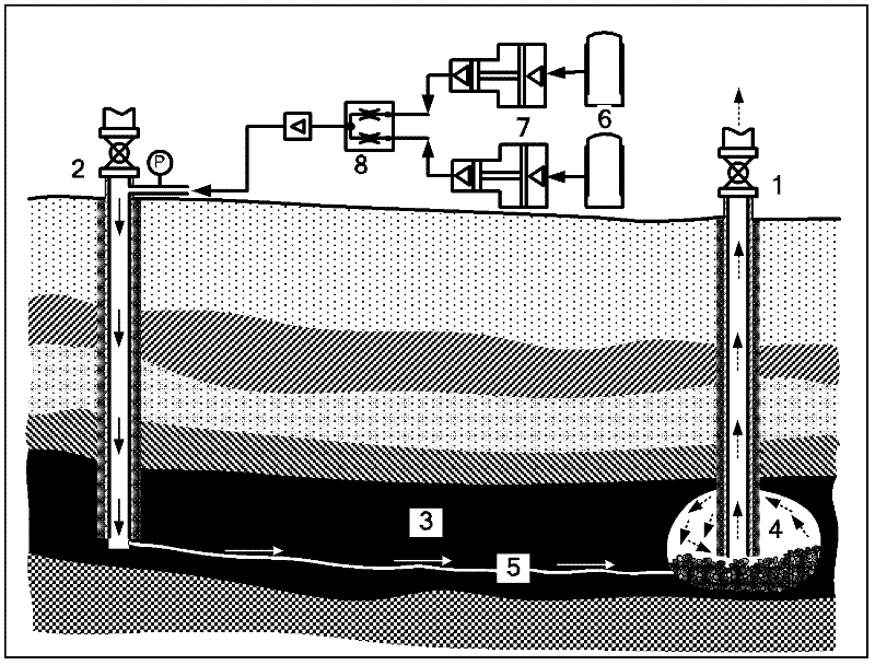
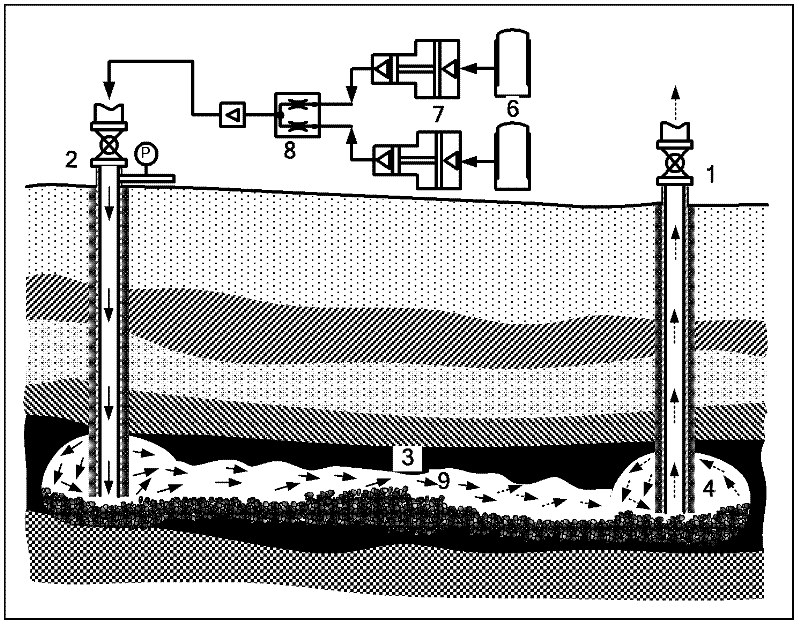
[0095] Such as Figure 1A , Figure 1B As shown, the existing vertical borehole 1 has a directional borehole 2 constructed at a distance of 200m from the borehole 1. It is planned to use the method of the present invention to establish a gasification channel and complete the gasification of coal in the area. The implementation process is as follows:

[0096]The fire zone 4 is established in the coal seam 3 at the bottom of the borehole 1 by means of electric ignition, and the temperature of the fire zone is controlled by adjusting the composition and flow rate of the gasification agent according to the water inflow of the coal seam and the gas outlet temperature. The temperature of the fire zone is generally not lower than that of the coal seam Auto-ignition temperature.

[0097] After the fire zone is established at the bottom of hole 1, directional drilling technology is used to construct a directional channel 5 along the coal seam via drill hole 2, and directly drill throug...

Embodiment 2

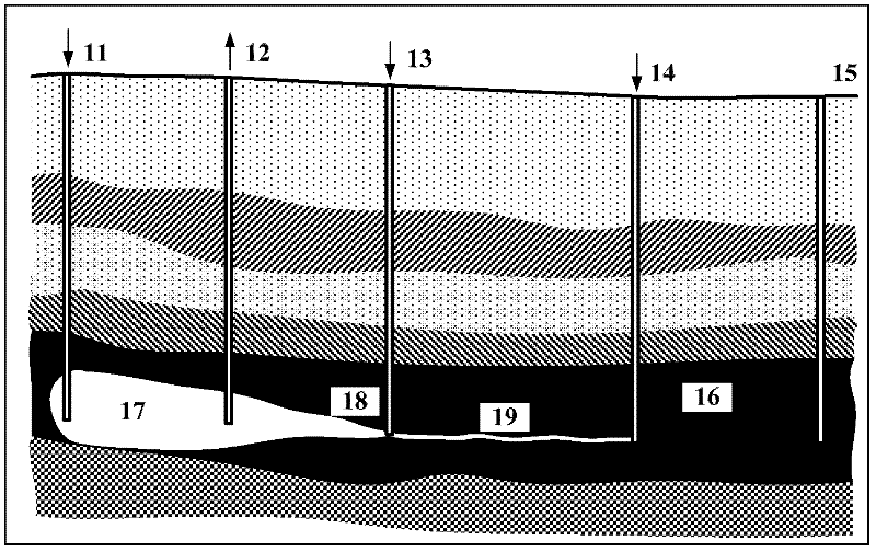
[0102] Such as figure 2 As shown, in the case of an underground coal gasification through-site, a plurality of boreholes 11, 12, 13, 14, 15 are provided, each of these boreholes is generally opened vertically, and these Drill holes along the horizontal direction ( figure 2 The left and right directions in the middle) are distributed at intervals with unequal intervals. The lower ends of each borehole deep into the underground coal seam area need to be connected in order to form the gasification channel required by the subsequent underground coal gasifier, among which, such as figure 2 As shown in the lower left of , the lower ends of the boreholes 11 and 12 have been penetrated (by air fire penetration in the prior art) and a gasification passage 17 in a substantially horizontal direction has been formed. It is planned to adopt the method of the present invention to continue the penetrating operation on the lower ends of the boreholes 12, 13, 14, and 15, and to accelerate...

Embodiment 3

[0114] Figure 3A , Figure 3B Shown is an example of an existing underground gasifier layout in which multiple vertical boreholes have been drilled. Select the lower end coal seam of borehole 22 to ignite, and form the fire area 21 of borehole 22, the lower end coal seam of existing borehole 23, 24, 25 needs to be penetrated, and after the penetration is completed, these vertical boreholes are used as vents. Boreholes 23, 24, and 25 are all vertical boreholes. The casing bottoms of these vertical boreholes are located 0.5m above the coal seam floor, and the borehole centers are basically on the same straight line (such as figure 2 Shown by the dotted line in the horizontal direction in A), wherein the spacing between the boreholes 23, 24, 25 is about 50m, and the spacing between the drilling holes 22, 23 is also about 50m. As described below, the directional drilling technology is used to penetrate the boreholes 23, 24, 25 along the coal seam to complete the docking with t...


PUM


Abstract

A passage formation method for underground coal gasification is provided. The method comprises the following steps of: (a) building a fire area in the bottom coal bed of a first bore hole; (b) performing mechanical and directional drilling operation in a neighbor coal bed close to the bottom of the first bore hole in the vicinity of the fire area through the lower end of a second bore hole which is another existing bore hole or a newly-drilled bore hole outside the fire area, so as to pre-penetrate the neighbor coal bed and thus to form a directional passage communicated with the fire area in the neighbor coal bed; and (c) delivering an oxygen-containing gas to the fire area through the second bore hole and the directional passage, and thermally processing the directional passage to enlarge the directional passage and thus to form a gasification passage used for a underground coal gasification furnace.

Description

technical field [0001] The invention relates to an underground coal gasification penetration method, and the method of the invention is applicable to the fields of underground coal gasification and the like. Background technique [0002] Underground coal gasification technology is to build a gasification furnace directly in the underground coal seam, feed gasification agent, and control the coal gasification reaction underground, so that the coal can be converted into combustible gas in the natural state in situ and transported to the ground process. [0003] The penetration is one of the key steps in the construction process of the underground gasifier. The so-called penetration is the process of artificially constructing a high-permeability channel along the coal seam at the bottom of the gas inlet and outlet drilling holes before the gasification process starts, so as to ensure smooth flow to the coal seam. Supply gasification agent and discharge coal gas from coal seam,...

Claims


Application Information

Patent Timeline
Patent Type & Authority Applications(China)
IPC IPC(8): E21B43/295
CPCE21B43/243E21B43/295
Inventor 庞旭林陈峰王世鹏刘刚张树川张明
Owner ENN SCI & TECH DEV
Why Eureka
Try Eureka