Control Device

a control device and control technology, applied in mechanical control devices manual control with single control member, etc., can solve the problem that the control device is not particularly tolerant of variations in relative positioning, and achieve the effect of redundancy and reliability

Active Publication Date: 2012-02-02
PENNY & GILES CONTROLS
View PDF5 Cites 18 Cited by
  • Summary
  • Abstract
  • Description
  • Claims
  • Application Information

AI Technical Summary

Benefits of technology

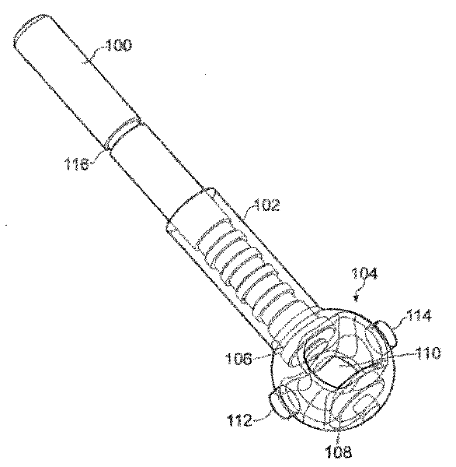
[0010]The control device may have a magnet arrangement which generates a magnetic field and a magnetic flux sensing unit which provides two dimensional angular orientation information with respect to that magnetic field. The relative orientation of the magnet arrangement and the magnetic flux sensing unit within a predetermined range of movement thus provides the user with a range of selectable positions which are translated by the control device into the user control signals. Whilst it is known to use a magnetic flux sensing unit configured to provide two dimensional angular orientation information with respect to a magnetic field generated by a permanent magnet, it is a feature of such arrangements that the relative positioning of the permanent magnet and the magnetic flux sensing unit is a critical design parameter, and furthermore that such control devices are not particularly tolerant to variations in that relative positioning that may occur as a result of mechanical loading or long-term wear. However, the inventors realised that by providing at least two permanent magnets configured to generate the magnetic field, the at least two permanent magnets could be arranged relative to the magnetic flux sensing unit such that as the magnetic flux sensing unit and magnet arrangement are reoriented relative to one another the magnetic field experienced by the magnetic flux sensing unit is substantially uniform throughout the range of movement. This arrangement provides a control device wherein the initial positioning (and ongoing positioning with age and wear) of the magnet arrangement and the magnetic flux sensing unit is less critical to the operation of the device and user control signals may be generated with greater reliability over a longer lifetime of the device.
[0030]In some embodiments said control device comprises a ferro-magnetic shield configured to shield said magnetic field surrounding said magnetic flux sensing unit from external influence. The configuration of the magnetic field provided by the magnet arrangement is an important factor in the construction of the control device, and a ferro-magnetic shield may help to avoid variations or disturbance in that magnetic field from an external source.

Problems solved by technology

Whilst it is known to use a magnetic flux sensing unit configured to provide two dimensional angular orientation information with respect to a magnetic field generated by a permanent magnet, it is a feature of such arrangements that the relative positioning of the permanent magnet and the magnetic flux sensing unit is a critical design parameter, and furthermore that such control devices are not particularly tolerant to variations in that relative positioning that may occur as a result of mechanical loading or long-term wear.

Method used


Image

  • Control Device
  • Control Device
  • Control Device

Examples


Embodiment Construction

[0043]FIGS. 3A, 3B and 3C schematically illustrate the magnet arrangement according to some exemplary embodiments. FIG. 3A shows a pair of ring magnets 60, 62 which are arranged coaxially with one another. Each ring magnet 60, 62 is also coaxially magnetised, having their respective axis of magnetisation aligned. This arrangement results in a magnetic field being generated, of which there is a region 64 located between the ring magnets across which the generated magnetic field is substantially uniform. This substantially uniform region of magnetic field may also be generated by magnet arrangements other than a pair of ring magnets. FIG. 3B schematically illustrates a magnet arrangement composed of 12 regions 70A-L, each having its magnetisation aligned at an angle to the magnetisation of its neighbour. Such an arrangement of magnets is sometimes known as a Halbach array. Within the cavity defined by the surrounding set of magnets 70 there is also a region 72 across which the magneti...


PUM

PropertyMeasurementUnit
diameteraaaaaaaaaa
diameteraaaaaaaaaa
diameteraaaaaaaaaa

Abstract

A control device is provided configured to provide user control signals. The control device comprises a magnetic flux sensing unit configured to provide two-dimensional angular orientation information with respect to a magnetic field acting on the magnetic flux sensing unit, and the user control signals are dependent on the two-dimensional angular orientation information. The control device further comprises a magnet arrangement comprising at least two permanent magnets configured to generate the magnetic field. The magnet arrangement and the magnetic flux sensing unit are arranged to be reoriented relative to one another within a predetermined range of movement, and the at least two permanent magnets are arranged relative to the magnetic flux sensing unit such that the magnetic field experienced by the magnetic flux sensing unit is substantially uniform throughout the predetermined range of movement.

Description

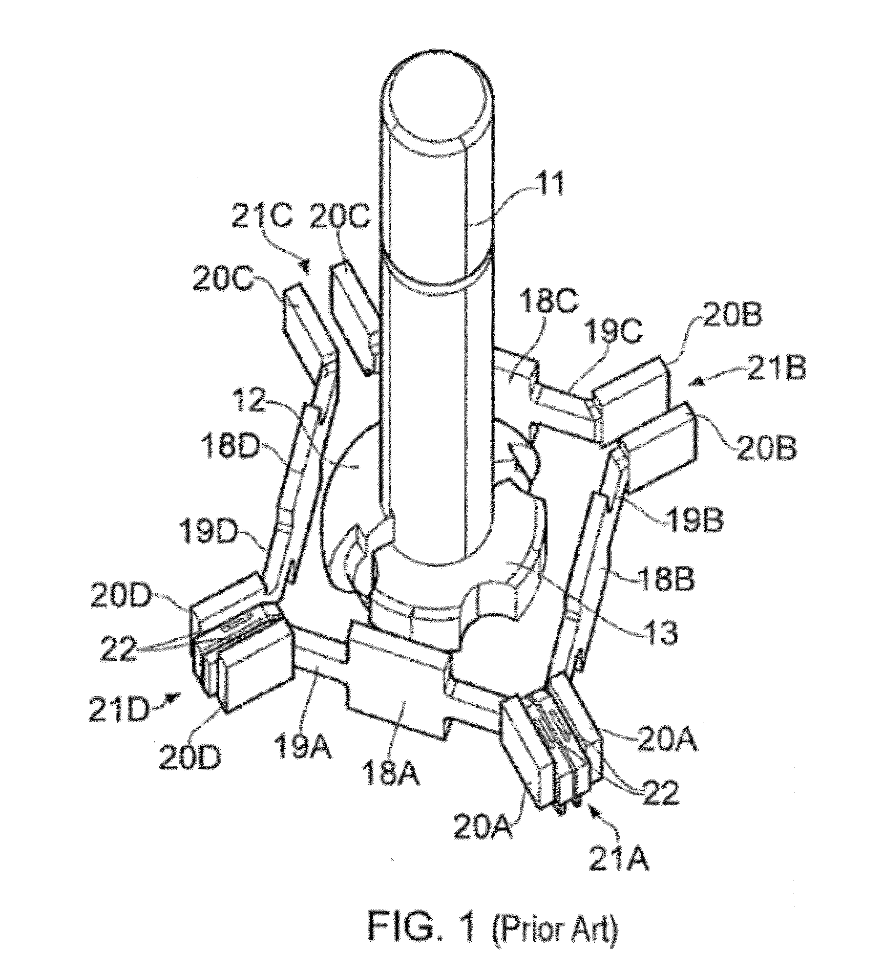
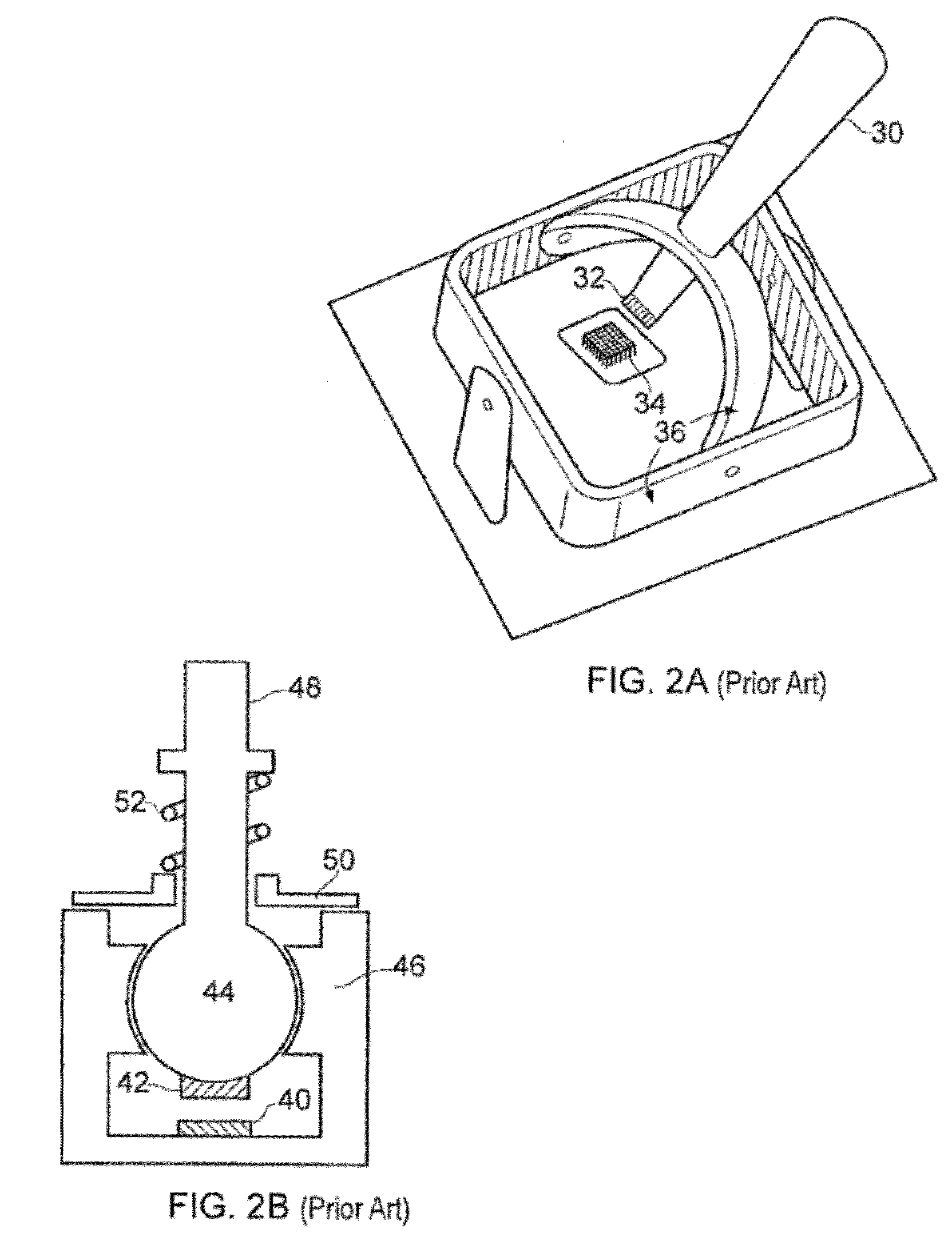
BACKGROUND OF THE INVENTION[0001]1. Field Of The Invention[0002]The present invention relates to control devices configured to provide user control signals, in particular control devices providing two dimensional control information such as a joystick.[0003]2. Description Of The Prior Art[0004]Control devices which provide user control signals based on the relative orientation of a magnetic flux sensor and a magnet are known. For example, a joystick may be constructed based on a familiar ball and socket arrangement, wherein a permanent magnet attached to the ball may be orientated with respect to a magnetic flux sensor mounted in the socket by means of a joystick handle protruding from the ball.[0005]One such joystick arrangement is disclosed in US Published Patent Application 2006 / 0028184 (and is schematically illustrated in FIG. 1). This arrangement comprises a shaft 11 forming the joystick handle terminating in a ball 12 which encloses a permanent magnet 13. The ball 12 is mounte...

Claims


Application Information

Patent Timeline
Patent Type & Authority Applications(United States)
IPC IPC(8): G01B7/30G01B7/14C22C5/06
CPCC22C5/06G01D5/12G05G9/047G01D5/145G05G7/02C22C1/02G01B7/00G05G9/00G05G2009/04755
Inventor BANERJEE, DEV KUMARDOWNS, CHARLES EDWARD
Owner PENNY & GILES CONTROLS
Why Eureka
Try Eureka