
Wind turbine rotor blade with precured fiber rods and method for producing the same

Inactive Publication Date: 2012-02-02
GENERAL ELECTRIC CO
View PDF17 Cites 75 Cited by
  • Summary
  • Abstract
  • Description
  • Claims
  • Application Information

AI Technical Summary

Problems solved by technology

In comparison to other parts of the blade, they are relatively heavy and typically contribute significantly to the weight of the rotor blade.

Method used


Image

  • Wind turbine rotor blade with precured fiber rods and method for producing the same
  • Wind turbine rotor blade with precured fiber rods and method for producing the same
  • Wind turbine rotor blade with precured fiber rods and method for producing the same

Examples


Embodiment Construction

[0034]Reference will now be made in detail to the various embodiments, one or more examples of which are illustrated in each figure. Each example is provided by way of explanation and is not meant as a limitation. For example, features illustrated or described as part of one embodiment can be used on or in conjunction with other embodiments to yield yet further embodiments. It is intended that the present disclosure includes such modifications and variations.

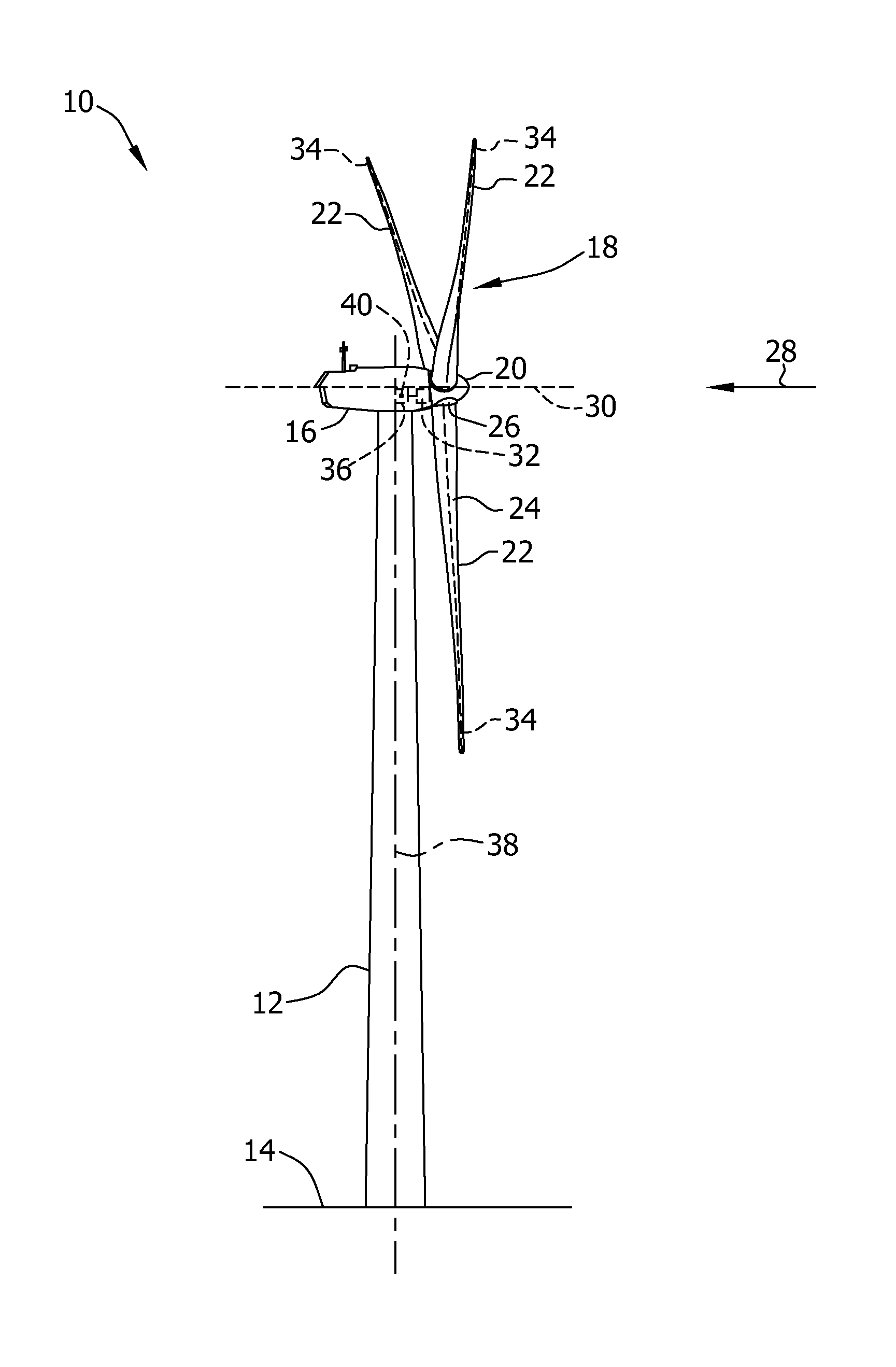
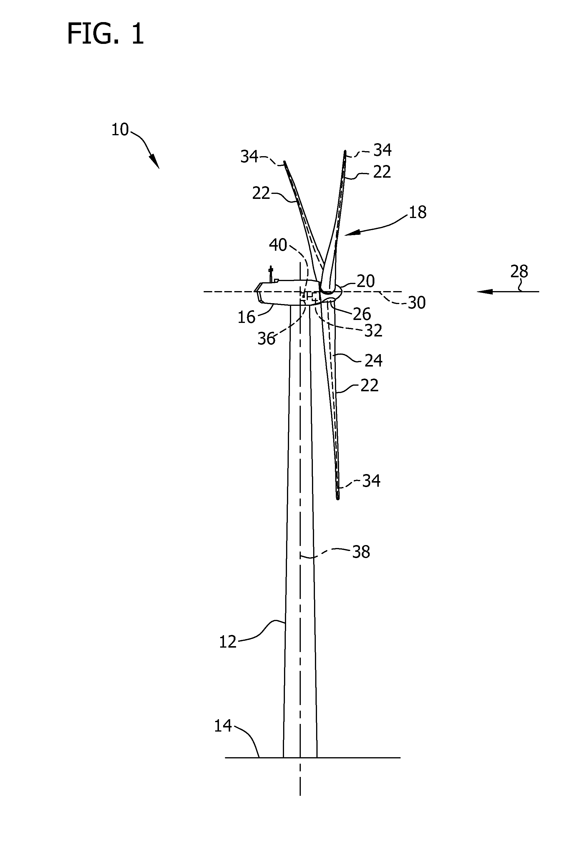
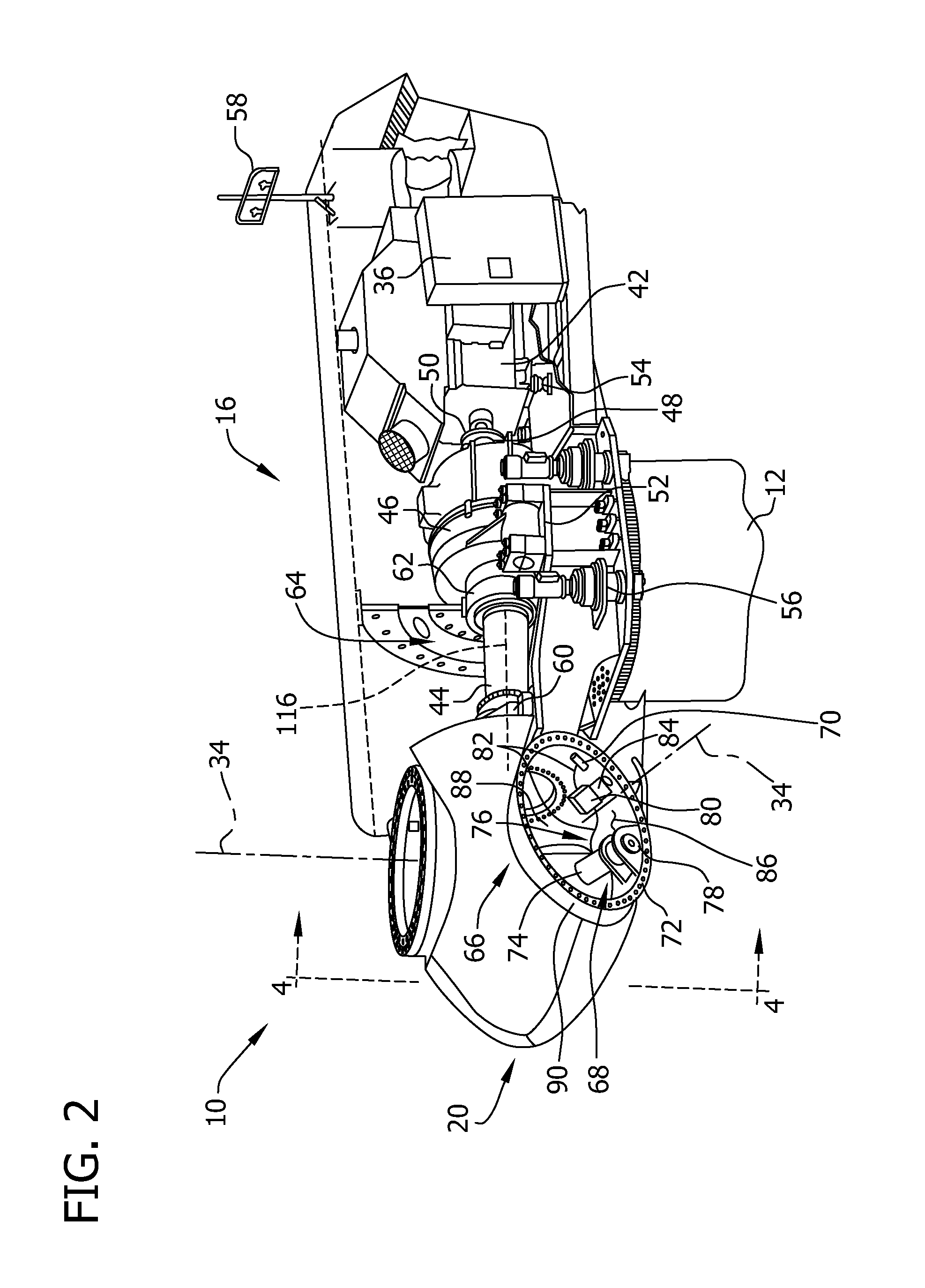
[0035]The embodiments described herein include a wind turbine system that has at least one rotor blade including pre-cured elements.

[0036]As used herein, the term “spar cap” is intended to be representative of an elongated structure which increases the strength of a wind turbine rotor blade. As used herein, the terms “injected” and “vacuum infused” are both intended to be representative for a method of inserting a resin into a layer of fibrous material. In technical applications, injection and vacuum infusion describe different ...


PUM

PropertyMeasurementUnit
Lengthaaaaaaaaaa
Thicknessaaaaaaaaaa
Shapeaaaaaaaaaa

Abstract

A wind turbine rotor blade comprises a rotor blade body, including a root portion, a leading edge, a trailing edge, and at least one spar cap; a plurality of parallel, elongated elements of a pre-cured composite material, which comprise fibers and a resin, and a resin connecting the plurality of elements. Further, a method for producing a rotor blade is provided.

Description

BACKGROUND OF THE INVENTION[0001]The subject matter described herein relates generally to methods and systems for wind turbine rotor blades, and more particularly, to methods and systems for the structural reinforcement of wind turbine rotor blades.[0002]At least some known wind turbines include a tower and a nacelle mounted on the tower. A rotor is rotatably mounted to the nacelle and is coupled to a generator by a shaft. A plurality of blades extend from the rotor. The blades are oriented such that wind passing over the blades turns the rotor and rotates the shaft, thereby driving the generator to generate electricity.[0003]Typically, the body of a wind turbine rotor blade includes a laminate of a resin and fiber material. Also structural elements like spar caps and the root portions of the rotor blade are fabricated in this manner. Typically, a spar cap is produced by inserting layers of glass fiber in a mold, and by subsequently inserting a resin in order to connect the layers a...

Claims


Application Information

Patent Timeline
IPC IPC(8): F01D5/14B23P15/02
CPCB29C70/86B29D99/0028B29L2031/085Y10T29/49337F05B2280/6003F05B2280/6015Y02E10/721F03D1/0675B29C70/541B29C70/545B29C70/547B29C2059/027B29C2793/0081Y02E10/72Y02P70/50
Inventor OGDE, PRASADAKHTAR, AFROZNIES, JACOB JOHANNES
Owner GENERAL ELECTRIC CO
Learn More