Fuel pump

a technology of fuel pump and fuel pump body, which is applied in the direction of pump, positive displacement liquid engine, machine/engine, etc., can solve the problems of increasing unable to disclose neither, and the manufacturing process of the electrical connection may become complicated, so as to reduce the number of manufacturing steps

Inactive Publication Date: 2012-02-02
DENSO CORP
View PDF1 Cites 31 Cited by
  • Summary
  • Abstract
  • Description
  • Claims
  • Application Information

AI Technical Summary

Benefits of technology

[0005]The present invention is made in view of the above problems. It is an object of the present invention to provide a fuel pump, according to which wiring of end portions of stator coils as well as electrical connection between those end portions can be easily done, so that a number of manufacturing steps can be reduced.

Problems solved by technology

However, any one of those prior arts discloses neither wiring of end portions of the stator coils forming multiple phases nor electrical connection between the end portions of the stator coils.
If each end portion of the stator coils is connected by manual procedures one by one, a manufacturing process for the electrical connection may become complicated and a number of manufacturing steps is increased.

Method used


Image

  • Fuel pump
  • Fuel pump
  • Fuel pump

Examples


Embodiment Construction

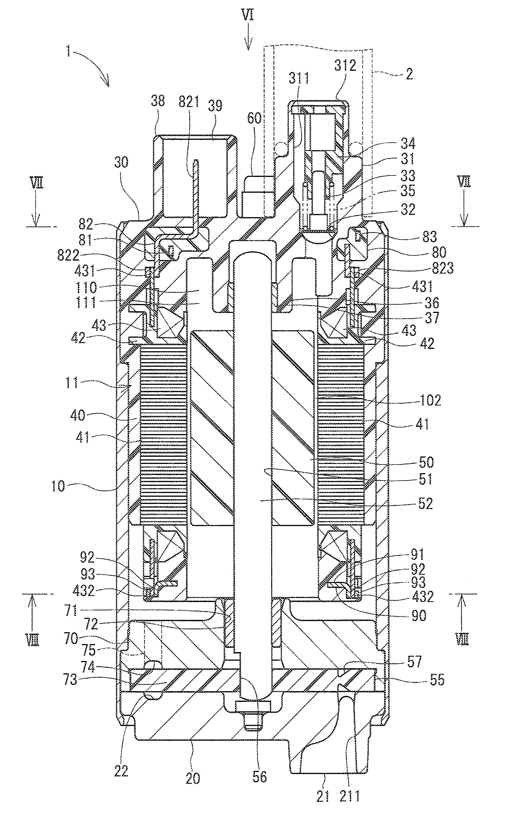
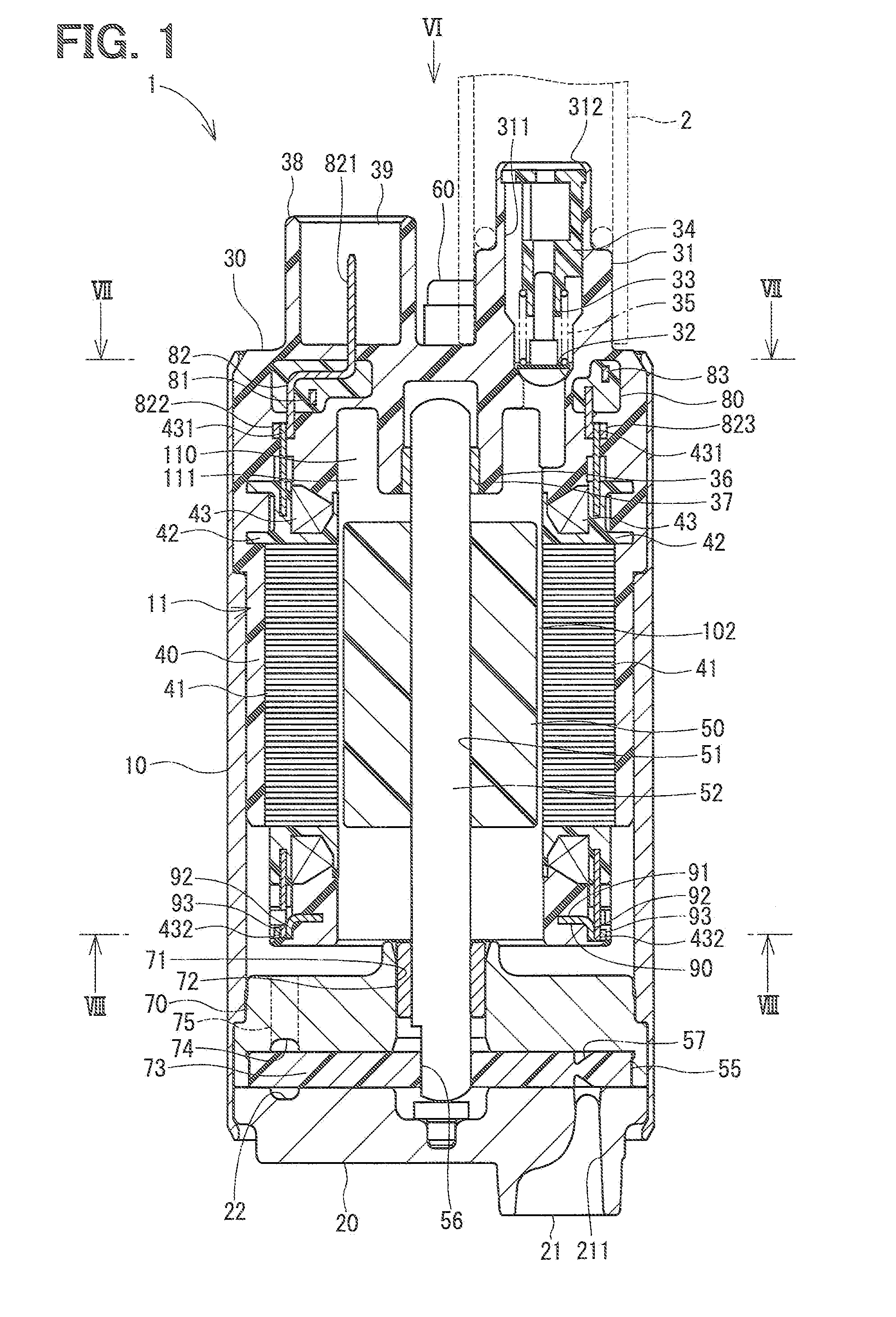
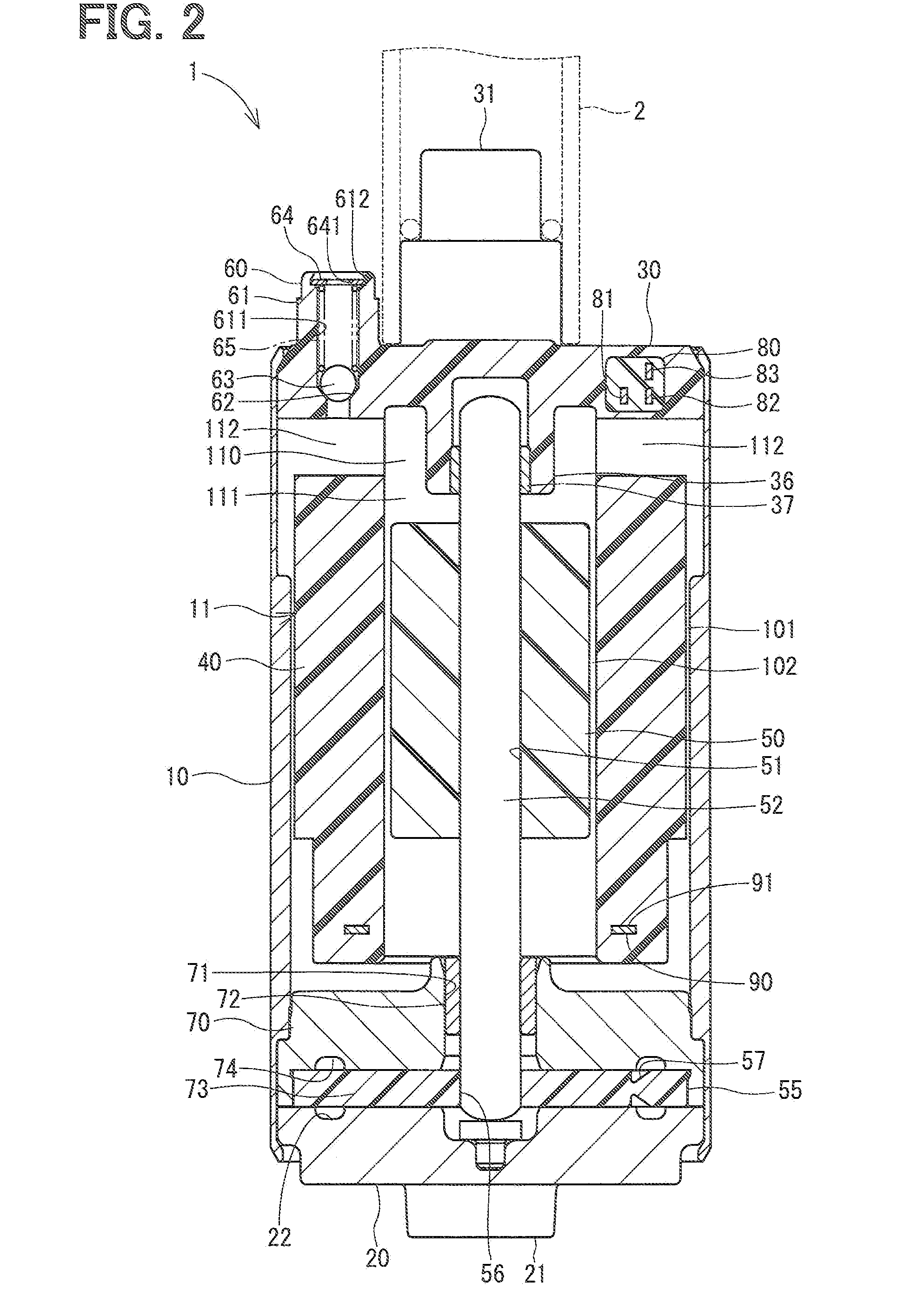
[0027]The present invention will be explained by way of embodiments with reference to the drawings. A fuel pump 1 according to an embodiment of the present invention is shown in FIG. 1 to FIG. 3C.

[0028]The fuel pump 1 draws fuel in a fuel tank (not shown) and supplies the fuel to an internal combustion engine. As shown in FIGS. 1 and 2, the fuel pump 1 has a housing 10, a pump cover 20, an end cover 30, a stator 40, a rotor 50, a shaft 52, an impeller 55, a pressure relief valve 60, a terminal sub-assembly 80, a neutral-point sub-assembly 90 and so on.

[0029]The housing 10 is made of metal, for example, iron, and is formed in a cylindrical shape. Plating, such as zinc plating, tin plating and so on, is treated on a surface of the housing 10.

[0030]The pump cover 20 is made of metal, for example, aluminum, and formed in a disc shape. The pump cover 20 closes one end (a lower end in FIG. 1) of the housing 10. A lower end portion of the housing 10 is inwardly bent in a radial direction, ...


PUM


Abstract

A fuel pump has a motor portion and a pump portion, wherein fuel is sucked from an inlet port into the pump portion when an impeller is rotated and the pressurized fuel is discharged out of the fuel pump from an outlet port. A stator has multiple stator cores on which respective stator coils are wound to form a star-connection winding. A terminal sub-assembly is provided in an axial side portion of the stator. The terminal sub-assembly has multiple conductive members and each end portion of the stator coils is respectively connected to connecting portions of the conductive members, which are arranged at equal intervals in a circumferential direction of the terminal sub-assembly.

Description

CROSS REFERENCE TO RELATED APPLICATION[0001]This application is based on Japanese Patent Application No. 2010-173385 filed on Aug. 2, 2010, the disclosure of which is incorporated herein by reference.FIELD OF THE INVENTION[0002]The present invention relates to a fuel pump for supplying fuel to, for example, fuel injection devices for an internal combustion engine.BACKGROUND OF THE INVENTION[0003]A fuel pump is conventionally known in the art, for example, as disclosed in Japanese Patent Publications No. 2005-110478, No. 2006-050808, and No. 2010-063344, according to which an impeller is rotated by a brushless motor to draw fuel from an inlet port and to pump out the fuel from an outlet port, so that the fuel is supplied to a device (for example, a fuel injection device for an internal combustion engine).[0004]According to the above prior arts, stator coils for a stator of a brushless motor as well as terminals, to which wires are connected for supplying electric power to the stator ...

Claims


Application Information

Patent Timeline
Patent Type & Authority Applications(United States)
IPC IPC(8): F04B35/04
CPCF04D5/002H02K3/522H02K5/12F04D13/0693H02K2203/03H02K2203/09H02K5/225
Inventor TANAHASHI, JYUNKINAGATA, KIYOSHI
Owner DENSO CORP
Why Eureka
Try Eureka