Marine vessel

a technology for marine vessels and stern steps, which is applied in the direction of marine propulsion, vessel construction, propulsive elements, etc., can solve the problems of easy air drawing (bubble biting) and no aisle connecting the stern steps on the left and right sides of the outboard motor, and achieve the effect of preventing reliably colliding and high convenien

Active Publication Date: 2012-02-02
YAMAHA MOTOR CO LTD
View PDF12 Cites 26 Cited by
  • Summary
  • Abstract
  • Description
  • Claims
  • Application Information

AI Technical Summary

Benefits of technology

[0040]With this arrangement of the present preferred embodiment of the present invention, the control device performs the moving-down step when the outboard motor is turned until the lower portion of the outboard motor moves from a position above the platform to a position below the platform. Specifically, the control device makes the lower portion of the outboard motor pass through the notched hole in the state in which the hatch is opened. Then, the control device detects passage of the lower portion of the outboard motor through the notched hole based on a detection value of the tilt detection mechanism in the moving-down step by performing the passage detection step. At this time, when passage of the lower portion of the outboard motor through the notched hole is detected, the control device performs the closing step after the passage is detected. Specifically, the control device closes the hatch by controlling the closing actuator. Thus, with this arrangement of the present preferred embodiment of the present invention, the hatch is automatically closed, so that a high level of convenience is obtained. Further, the hatch is closed after the lower portion of the outboard motor passes through the notched hole, so that the hatch is reliably prevented from colliding with the lower portion of the outboard motor. Accordingly, the hatch and the outboard motor are prevented from being broken or damaged.

Problems solved by technology

However, in the marine vessel according to the above-described prior art, no aisle connecting the stern steps disposed on the left and right sides of the outboard motor is provided.
Therefore, a flow of water flowing from a water drain surface of the lower portion of the transom is directly caught by a propeller of the outboard motor and air drawing (bubble biting) easily occurs.

Method used


Image

  • Marine vessel
  • Marine vessel
  • Marine vessel

Examples


first preferred embodiment

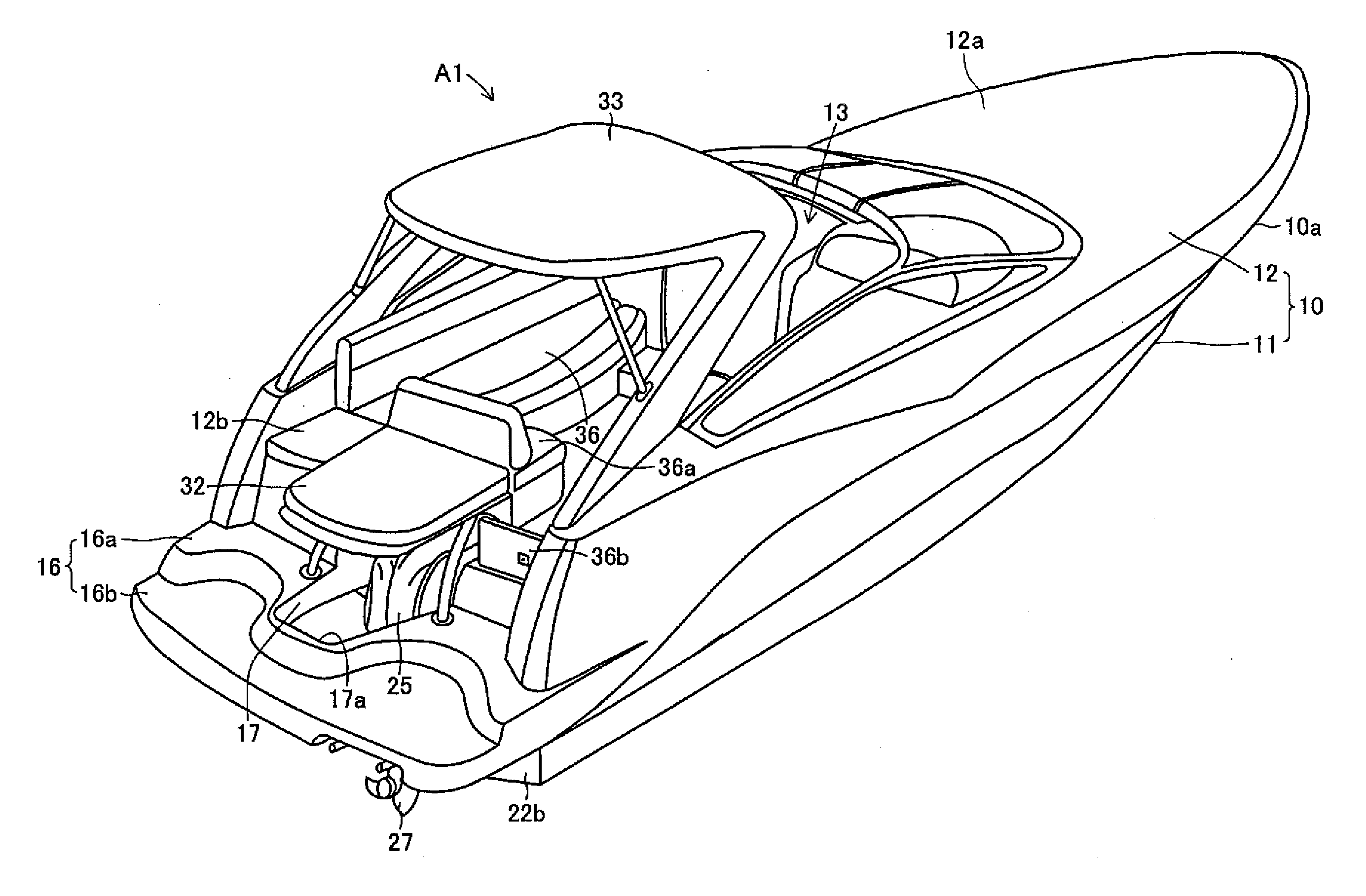
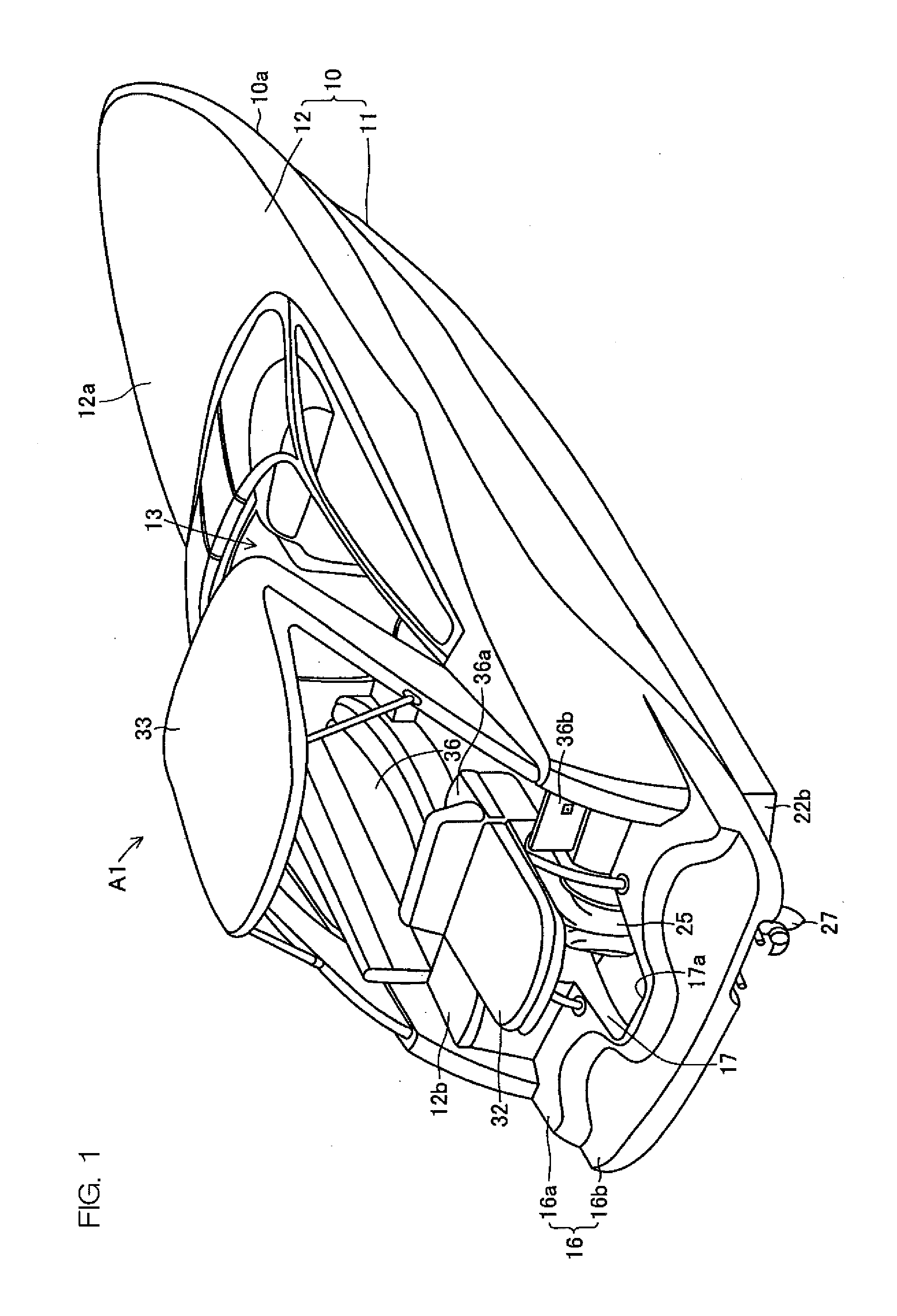
[0071]FIG. 1 to FIG. 3 show a cruiser type marine vessel A according to a first preferred embodiment of the present invention.

[0072]A hull 10 of the marine vessel A1 includes a body 11 including a hull bottom portion and a deck 12. The peripheral edge portions of the body 11 and the deck 12 are joined to each other in a watertight manner. On the periphery of the hull 10, a gunwale portion 10a is provided. Further, a cockpit 13 whose periphery is open is provided from the substantially center in the front-rear direction of an upper portion to a rear portion of the hull 10. On the starboard side inside the cockpit 13, a steering mechanism 14 and a driver's seat 15 are provided alongside in the front-rear direction. Near the steering mechanism 14, various devices necessary for steering the marine vessel A1, such as a start switch, gauges, and an accelerating and decelerating operation lever are provided.

[0073]At a front-side portion forward relative to the cockpit 13 on the upper surfa...

second preferred embodiment

[0104]Hereinafter, a marine vessel A2 according to a second preferred embodiment of the present invention will be described in detail with reference to FIG. 9 to FIG. 20. A major difference between this second preferred embodiment and the above-described first preferred embodiment is that the hatch 203 arranged to be capable of closing the notched hole 213 is attached to the platform 202. In FIG. 9 to FIG. 20, components equivalent to the components shown in FIG. 1 to FIG. 8 described above are denoted by the same reference numerals as in FIG. 1, etc., and description thereof will be omitted.

[0105]FIG. 9 and FIG. 10 are perspective views of the stern of the marine vessel A2 according to the second preferred embodiment of the present invention. FIG. 11 is a partial sectional view of the stern of the marine vessel A2 taken along line XI-XI in FIG. 12, and FIG. 12 is a plan view of the stern of the marine vessel A2. FIG. 9 shows a state in which the hatch 203 is closed. FIG. 10 shows a...

third preferred embodiment

[0147]FIG. 21 is a plan view of a hatch 203 and components relating thereto provided in the marine vessel A3 according to a third preferred embodiment of the present invention. FIG. 22 is a sectional view of the hatch 203 and components relating thereto taken along line XXII-XXII in FIG. 21. In FIG. 21 and FIG. 22, components equivalent to the components shown in FIG. 1 to FIG. 20 described above are denoted by the same reference numerals as in FIG. 1 and description thereof will be omitted. In FIG. 21 and FIG. 22, an illustration of the opening / closing detection mechanism 224 (refer to FIG. 16) is omitted.

[0148]A major difference between the third preferred embodiment and the above-described second preferred embodiment is that the hatch 203 is arranged to be automatically opened. The marine vessel A3 includes two pressing members 301, the above-described lock mechanism 225, and two actuators 302 (opening actuators). In the present preferred embodiment, the lock mechanism 225 and th...


PUM


Abstract

A marine vessel includes an outboard motor mounting portion provided at a stern of a hull, an outboard motor locating hole provided rearward of the outboard motor mounting portion and near the outboard motor mounting portion and penetrating vertically through the stern, a platform provided rearward of the outboard motor locating hole, and an outboard motor located in the outboard motor locating hole and mounted to the outboard motor mounting portion. This structure enables an occupant of the marine vessel to freely move in a space around the outboard motor on the platform and use the space.

Description

BACKGROUND OF THE INVENTION[0001]1. Field of the Invention[0002]The present invention relates to a marine vessel that is propelled by an outboard motor.[0003]2. Description of the Related Art[0004]So-called cruiser type marine vessels to be used for leisure, etc., are known. An example of such marine vessels is a marine vessel that is propelled by an outboard motor (for example, refer to Japanese Published Unexamined Patent Application No. H09-207888). This marine vessel is propelled by an outboard motor disposed outside the hull, so that a space for locating a driving engine is not necessary inside the hull. Therefore, in the marine vessel, a space for installing various devices and a space for relaxing are wider than in other types of marine vessels with substantially the same size.[0005]A marine vessel according to the above-described prior art has an outboard motor mounting portion provided on the transom. An outboard motor provided in the marine vessel is mounted to the outboar...

Claims


Application Information

Patent Timeline
Patent Type & Authority Applications(United States)
IPC IPC(8): B63H20/08B63B19/14B63B17/00B63H20/02
CPCB63B3/48B63B29/02B63B2003/485B63B2029/043B63H20/22B63H20/08B63H20/10B63B19/14B63H5/125B63H20/04
Inventor MOCHIZUKI, YASUSHINAKAZONO, YOSHIFUMIIHARA, HIROHIDEMOUE, TAKAYUKI
Owner YAMAHA MOTOR CO LTD
Why Eureka
Try Eureka