Optical Cap for Use With Arthroscopic System

a technology of arthroscopic system and optical cap, which is applied in the field of arthroscopic surgical instruments, can solve the problems of reducing the efficiency of arthroscopic system, and wasting a large amount of space between the square chip and the circular arthroscope, so as to reduce the cost, and reduce the risk of damag

Inactive Publication Date: 2012-02-02
CANNUFLOW INC
View PDF3 Cites 21 Cited by
  • Summary
  • Abstract
  • Description
  • Claims
  • Application Information

AI Technical Summary

Benefits of technology

[0006]The devices and methods described below provide for an arthroscope having square or rectangular lateral cross section herein after referred to as a rectangle or rectangular. The arthroscope can be used in an arthroscopic system that also includes a scope sheath that is matched to the dimensions of the arthroscope. The system includes a flow system, which sends fluid out of the end of the endoscope and brings debris and other fluid behind the field of view, thus allowing the surgeon to have a clear field of view while using the system.
[0007]This architecture allows the arthroscope to have a low profile thus making it less traumatic once introduced into anatomic spaces. Further, configuring the arthroscopic cross-section into the shape of the pre-manufactured CCD chip image configurations reduces costs associated with the manufacture of the scope.
[0008]To enhance the effectiveness of the systems, the arthroscope includes a protective cap for use over the distal tip of the arthroscope. The cap is constructed of a non-conductive polymer. The portion of the c...

Problems solved by technology

When the chips are housed within the arthroscope, this results in a great amount of wasted space between the square chips and the circular arthroscope that houses the chips.
In addition,...

Method used


Image

  • Optical Cap for Use With Arthroscopic System
  • Optical Cap for Use With Arthroscopic System
  • Optical Cap for Use With Arthroscopic System

Examples


Embodiment Construction

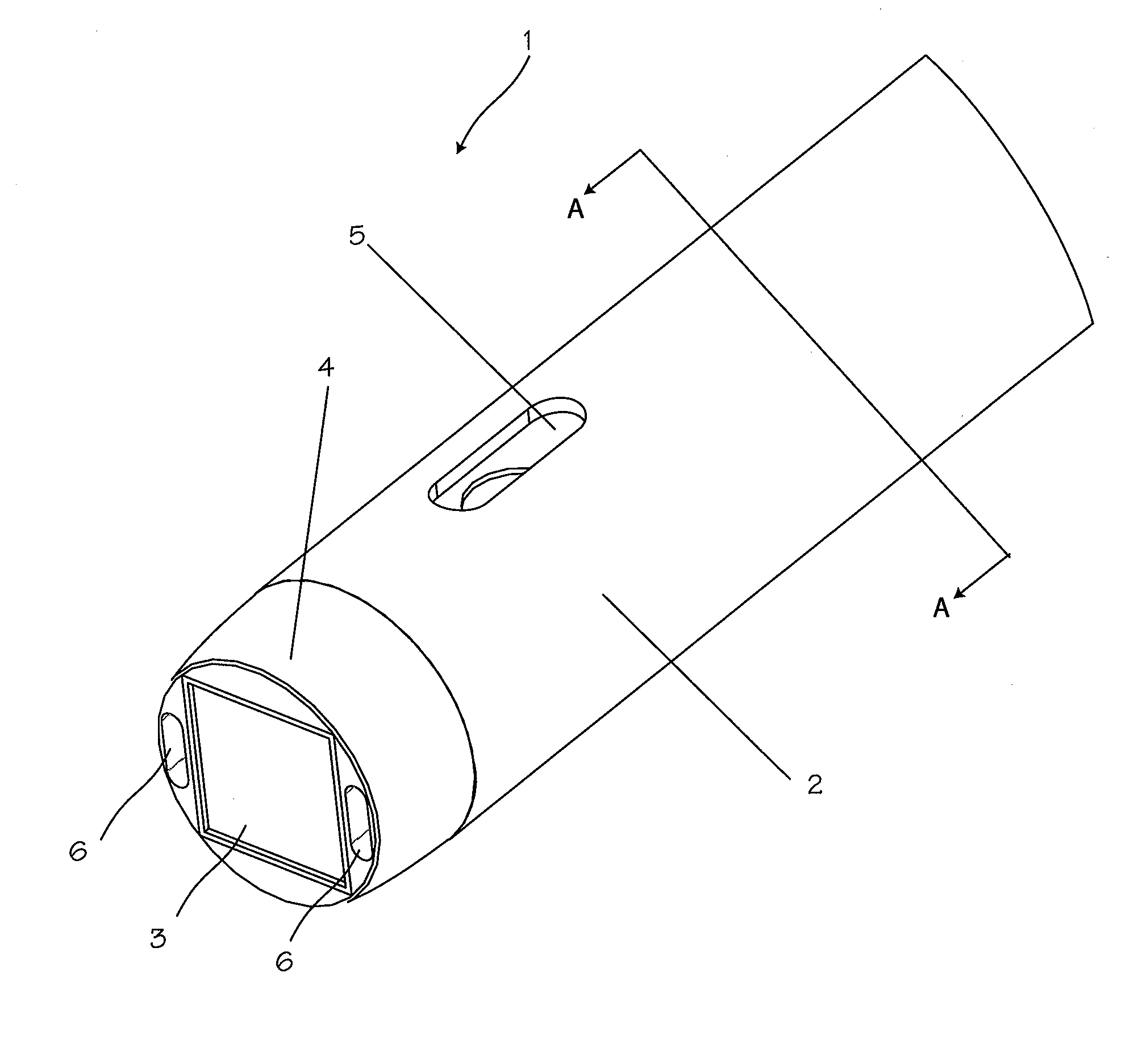
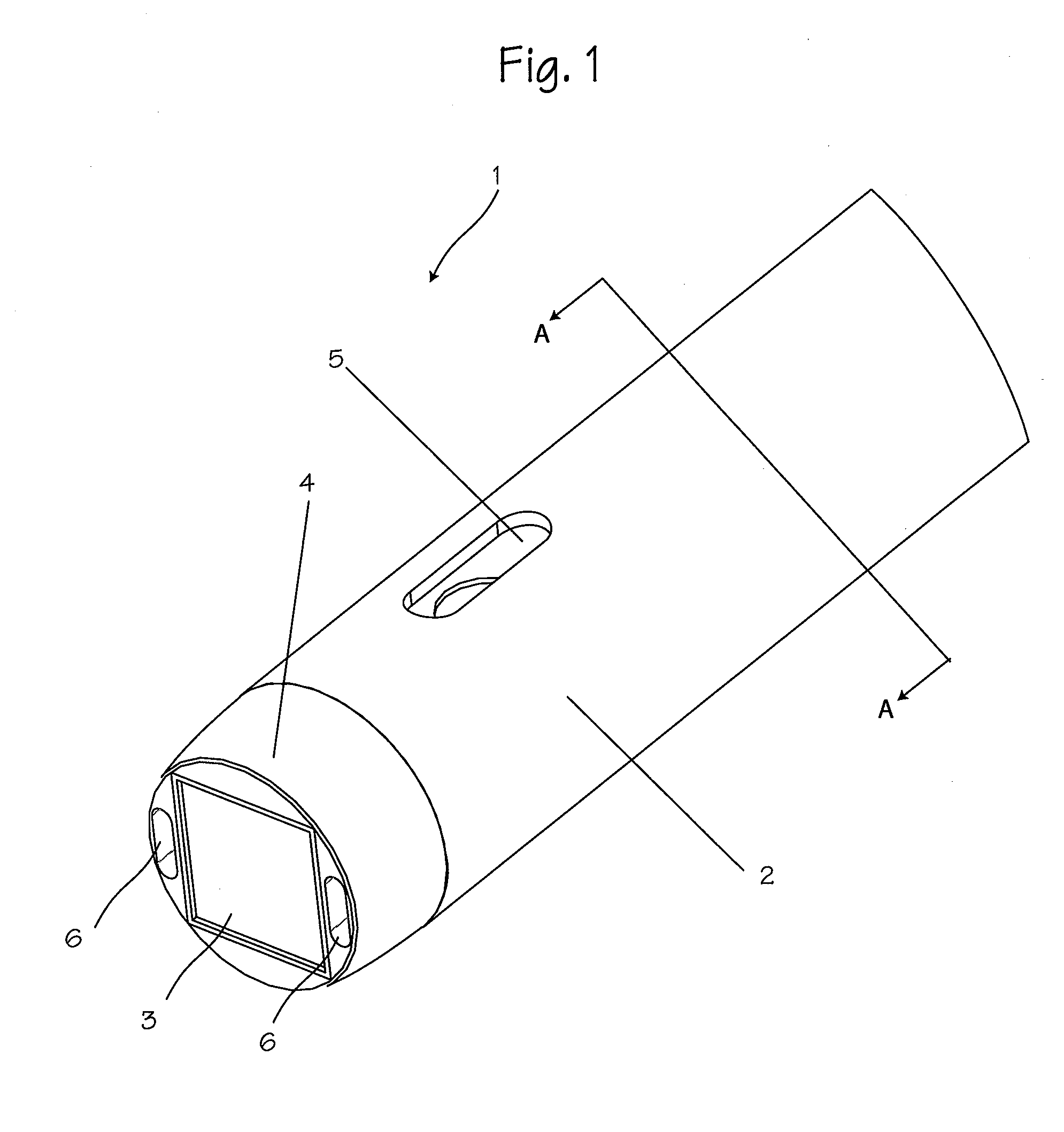
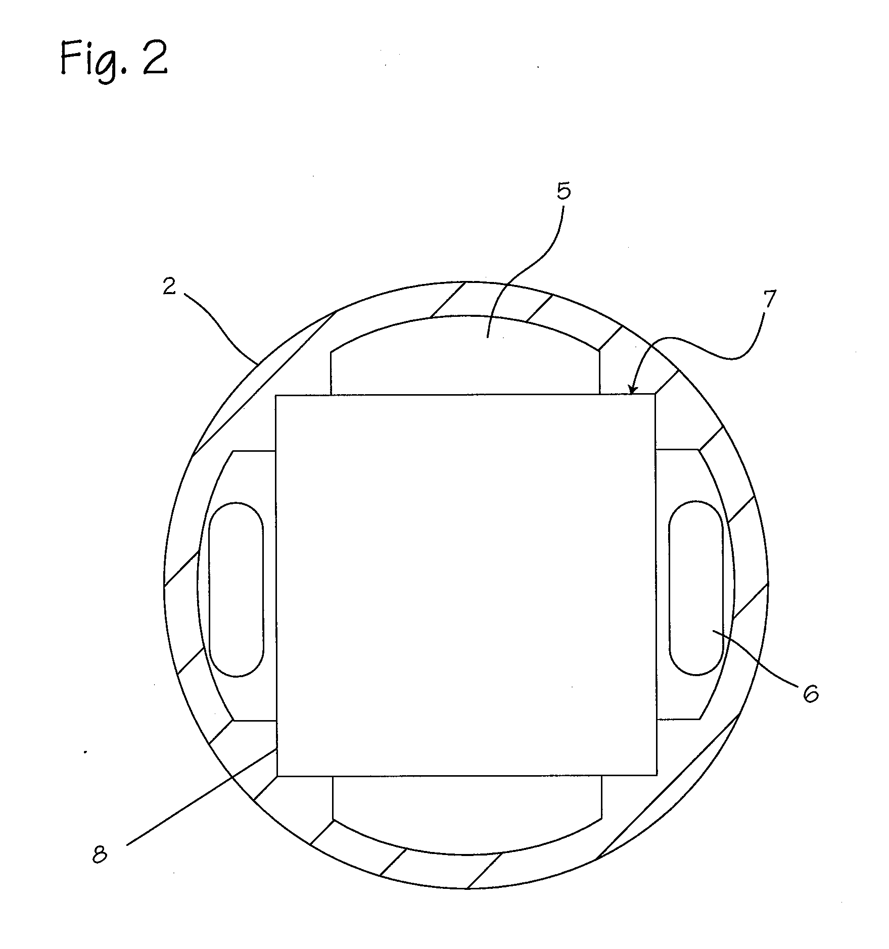
[0024]FIG. 1 shows an arthroscope 1 having a sheath that encloses an elongated core having a square radial cross section (see FIG. 2). Contained centrally within a sheath 2, the elongated core has a square imaging chip 3 located at the distal end of the elongated core. The elongated core and the imaging chip together form the imaging core of the arthroscope. An atraumatic tip 4 at the distal end may also encase the imaging chip. The elongated core has a square radial cross section that allows for the largest possible rectangular chip image package to be used in combination with the smallest possible round fluid sheath outside diameter. This combination allows a clear pocket flow system, which sends fluid out of the end of the arthroscope and brings debris and blood behind the operator's field of view. The system contains fluid outflow 5 and fluid inflow channels 6. These channels are defined by the space created between the elongated core and the circular sheath surrounding it.

[0025...


PUM


Abstract

An optical cap for use with an arthroscope system and its features.

Description

[0001]This application is a continuation in part of application Ser. No. 12 / 846,747 filed on Jul. 29, 2010.FIELD OF THE INVENTIONS[0002]The inventions described below relate to the field of arthroscopic surgical instruments.BACKGROUND OF THE INVENTIONS[0003]Arthroscopic surgery involves using optical instruments, such as an arthroscope, to visualize an operating field inside or near a joint of a patient. The same instrument or other instruments may be used to perform a surgical procedure in the operating field.[0004]Known inflow and outflow arthroscope systems generally consist of several elements, which include a flexible or rigid tube, a light that illuminates the area the doctor wants to examine (where the light is typically outside of the body and delivered via an optical fiber system), a lens system that transmits an image to the viewer from the arthroscope and another channel that allows the entry of medical instruments or manipulators. The lens systems typically use pre-manuf...

Claims


Application Information

Patent Timeline
IPC IPC(8): A61B1/12
CPCA61B1/00089A61B1/05A61B1/00183A61B1/317
Inventor KUCKLICK, THEODORE R.
Owner CANNUFLOW INC
Why Eureka
Try Eureka