Two chamber syringe with locking mechanism

a technology of locking mechanism and syringe, which is applied in the direction of intravenous devices, medical devices, other medical devices, etc., can solve the problems of increased chance of medical errors, time sensitive, and problematic left over medication, and achieve the effect of improving the standard of care and cost-effectiveness

Inactive Publication Date: 2012-02-02
BEE SIGHT LLC
View PDF6 Cites 37 Cited by
  • Summary
  • Abstract
  • Description
  • Claims
  • Application Information

AI Technical Summary

Benefits of technology

[0019]A cost-effective single syringe that both administers medication and flushes the intravenous system is needed to improve the standard of care. It is desirable to allow caregivers to follow their standard syringe filling procedures; to not rely on the fluid in the distal chamber to expel the primary fluid (medicine) from the syringe; to include a physical locking mechanism such that the intermediate fluid cannot be expelled accidentally while depressing the plunger during routine filling; to allow filling of the distal chamber from the proximal end (during manufacturing), which enables complete filling of the distal chamber without trapping any large / non injectable air bubbles; to utilize basic fluid mechanics to keep the two fluids separate when disposed within the syringe; and to not limit the volume of medicine that can be filled into the proximal chamber.

Problems solved by technology

This leftover medication is problematic for several reasons.
First, it necessarily means that the entire amount of medicine drawn into the syringe does not reach the patient.
Second, many medications are time sensitive and should not remain in the catheter until a subsequent medicine flushes it through.
For instance, by using a separate syringe for each injection, there is an increased chance of medical error.
Most medicines are colorless (like the saline solution), and it is easy to accidentally administer medication when intending to flush the line or vice versa.
This risk is increased when clinicians carry medicines for multiple patients at one time.
The likelihood of error is compounded in an emergency, when it may be necessary to inject several medications quickly and in a specific order.
In such situations, a separate saline flush is necessary between every individual medication injection, so the risk of error is high, and the consequences of a mistake may be grave.
Even if all precautions are taken and the two injections are made in the proper order, drawbacks remain.
With each breach of the catheter's seal for injection, the patient is potentially exposed to bacteria, increasing the risk of infection.
Using a second syringe for the saline flush also wastes resources.
Attaching a second syringe to the catheter takes time, and since a clinician may perform a saline flush more than one hundred times per day, this lost time adds up quickly.
Finally, requiring a second syringe unnecessarily increases the already significant costs related to manufacturing, shipping, storage, and disposal of syringes.
However, due to design limitations, no syringe has become widely accepted that allows routine medication administration and subsequent catheter flushing from a single syringe.
The previously described syringes adapted to deliver multiple fluids have not been widely adopted because they generally require the delivery of two fluids that are both prefilled during manufacturing.
Requiring hospitals to change their practice to using previously described multi-fluid syringes is unfeasible because the hospitals would be required to keep an unreasonable number of prefilled medicine syringes in stock to accommodate the varied number of doses and types of medications required for routine patient care.

Method used


Image

  • Two chamber syringe with locking mechanism
  • Two chamber syringe with locking mechanism
  • Two chamber syringe with locking mechanism

Examples


Embodiment Construction

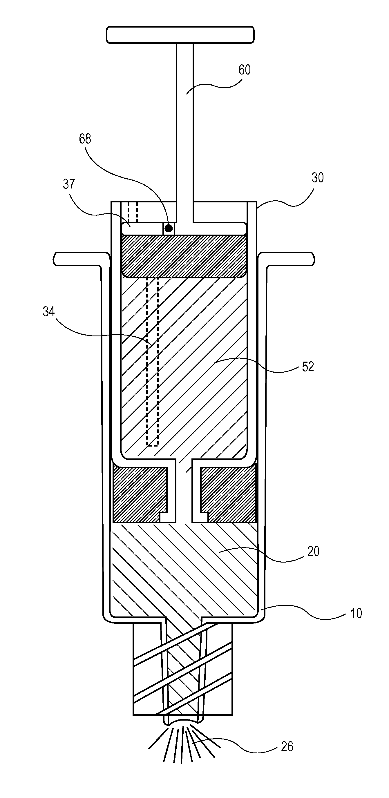
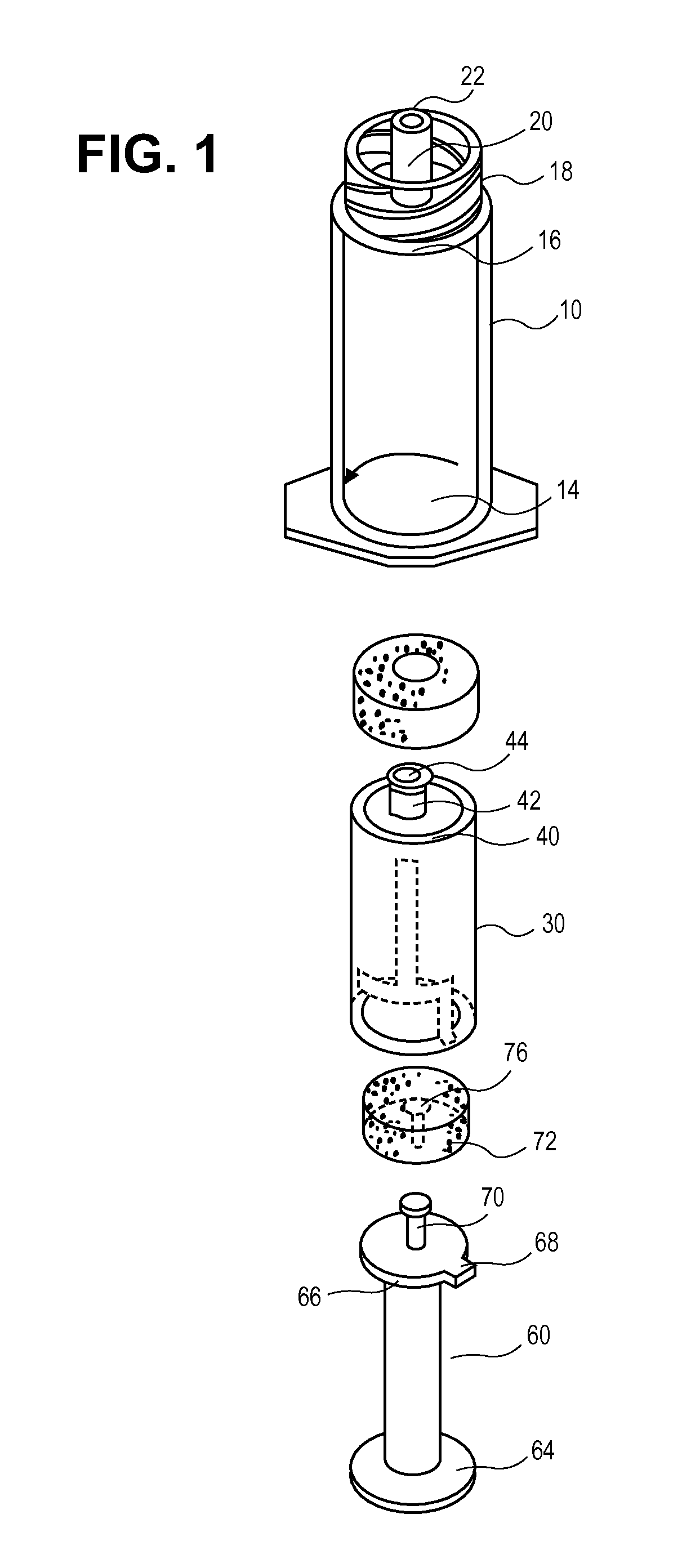
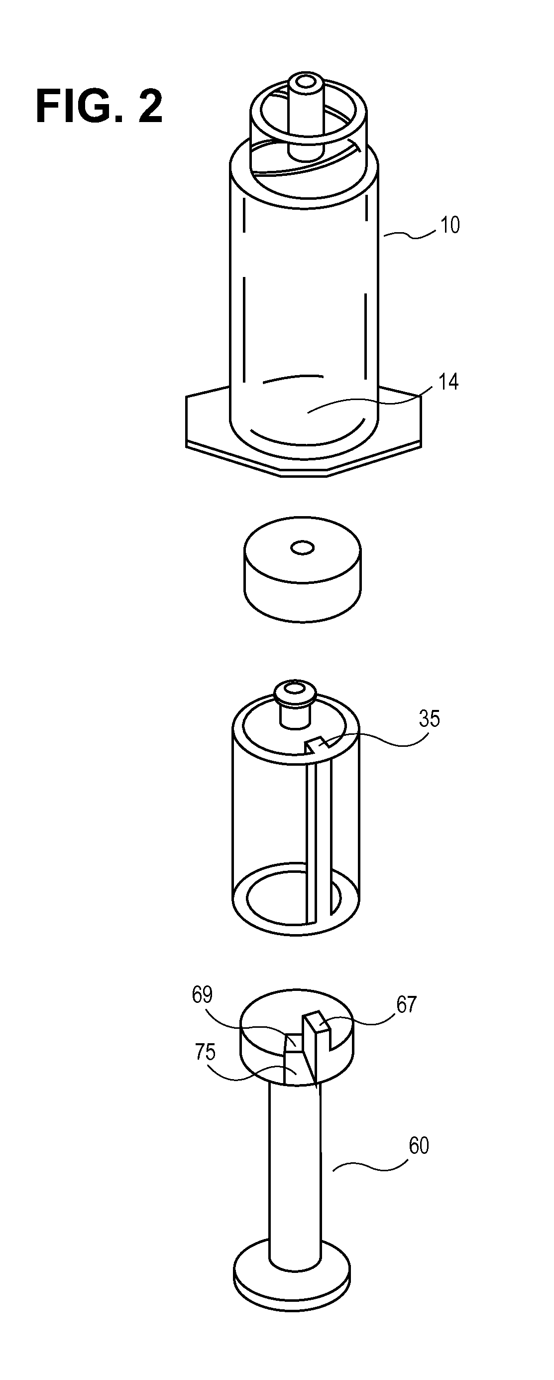
[0049]Described herein are syringe devices, systems and methods. In general, the syringe may include a second chamber and a cartridge movable within the second chamber. The cartridge includes a cartridge chamber (first chamber), a first end that defines a conduit in fluid communication with the cartridge chamber and the second chamber, a liquid disposed within the cartridge chamber such that there is a liquid-air interface at or within the conduit, wherein the liquid has a fluid property such that the liquid-air interface, cooperating with the conduit and the fixed volume of the cartridge, prevents movement of the liquid out of the conduit, a second end, movable within the cartridge chamber, and a locking mechanism having a locked configuration and an unlocked configuration, the locking mechanism preventing movement of the second end within the cartridge chamber while in the locked configuration. In general, the methods of filling a syringe during manufacturing may include the steps...


PUM


Abstract

A syringe includes a cartridge and a second chamber. The cartridge includes a first chamber, a second end, and a locking mechanism. The second end is movable within the first chamber between a first position and a second position. The locking mechanism has a locked configuration and an unlocked configuration and prevents movement of the second end within the first chamber while in the locked configuration. The locking mechanism includes: a flexible arm having a first end coupled to the second end of the cartridge and a second free end; a tab coupled to the second free end; and a groove in the inner surface of the chamber configured to receive the tab. The cartridge is moveable within the second chamber.

Description

INCORPORATION BY REFERENCE[0001]All publications and patent applications mentioned in this specification are herein incorporated by reference to the same extent as if each individual publication or patent application was specifically and individually indicated to be incorporated by reference.BACKGROUND OF THE INVENTION[0002]1. Field of the Invention[0003]This invention relates to syringe injectors.[0004]2. General Background[0005]Syringes are commonly used in the medical field for the injection or withdrawal of liquid medications. Syringes typically have a hollow glass or plastic barrel with an internal piston. By moving the piston, a user can create a positive or negative pressure inside the barrel, thereby transmitting fluid out of or into the barrel through a small opening opposite the piston.[0006]Syringes are often used in intravenous therapy where the syringe may directly puncture the vein, or more commonly, may be used in conjunction with a catheter. When a catheter is used, ...

Claims


Application Information

Patent Timeline
Patent Type & Authority Applications(United States)
IPC IPC(8): A61M5/31
CPCA61M5/31596A61M5/19
Inventor LEE, MARTIN N.WILLIS, GOEFFREY H.CHRISTIAN, JEFFREY J.
Owner BEE SIGHT LLC
Why Eureka
Try Eureka