Robotic mower home finding system

Active Publication Date: 2012-02-02
DEERE & CO
View PDF8 Cites 43 Cited by
  • Summary
  • Abstract
  • Description
  • Claims
  • Application Information

AI Technical Summary

Benefits of technology

[0003]A robotic mower home finding system includes a charging station connected to an outer boundary wire, and a vehicle control unit on the robotic mower that changes the path of the robotic mower each time it returns home to the charging station. The vehicle

Problems solved by technology

Robotic mowers may damage the turf along a boundary wire or border when the robotic mower returns home to the charging station.
Repeatedly

Method used


Image

  • Robotic mower home finding system
  • Robotic mower home finding system
  • Robotic mower home finding system

Examples


Embodiment Construction

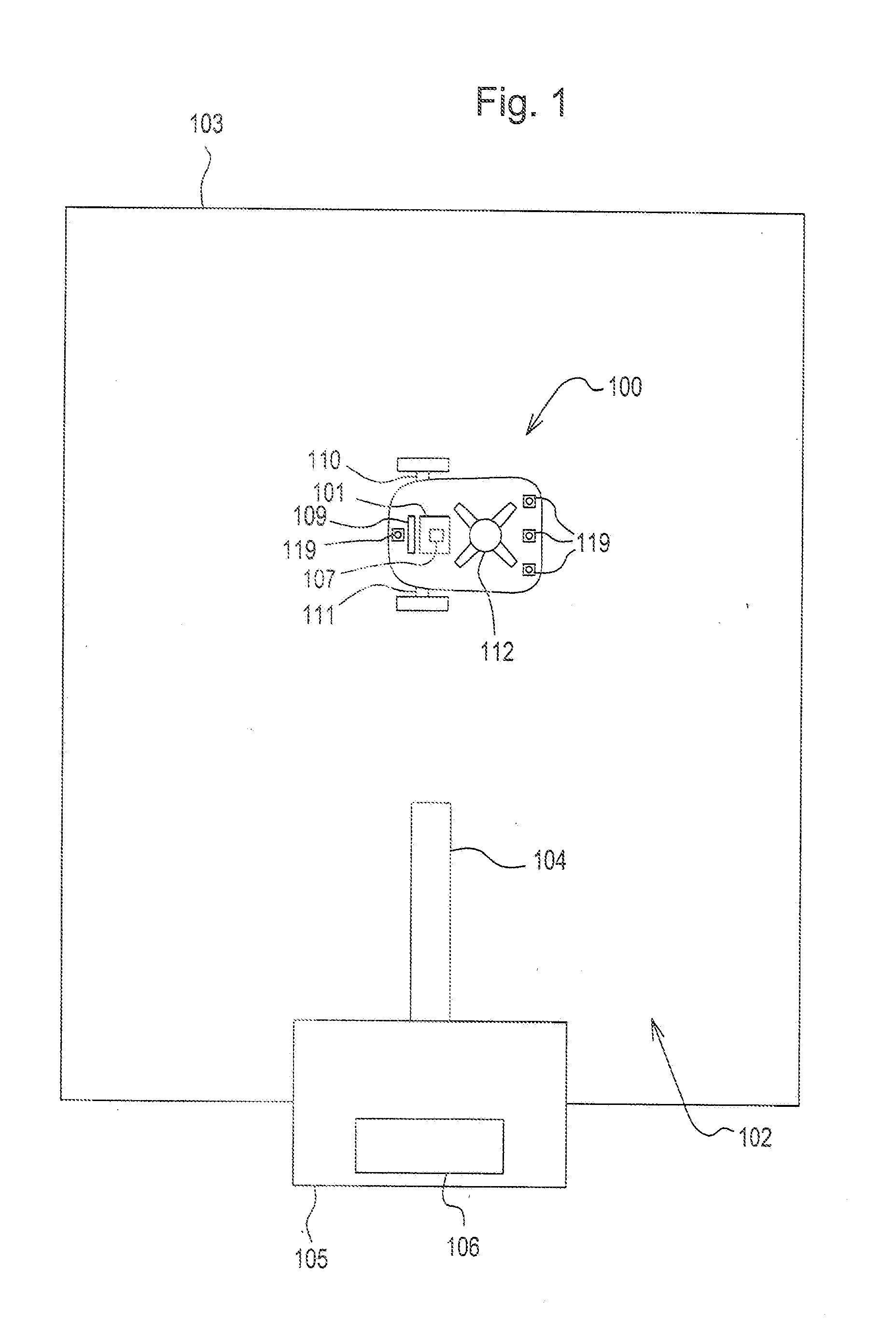
[0015]In one embodiment shown in FIG. 1, robotic mower 100 may be powered by battery pack 109 that may be charged periodically at charging station 105. Vehicle control unit 101 may control all of the electronic functions of the robotic mower. For example, vehicle control unit 101 may command a pair of traction motors 110, 111 to turn traction drive wheels, blade motor 112 to rotate a cutting blade or blades, battery pack 109, a user interface and various sensors.

[0016]Vehicle control unit 101 may be a printed circuit board assembly that serves as the main control board for the robotic mower. The vehicle control unit may interpret and process information from various sensors, and use that information to control and operate the pair of traction motors to drive the robotic mower over a yard in order to maintain the lawn, and to drive the blade motor. For example, the vehicle control unit may be connected to a number of sensors including one or more boundary sensors 119, as well as one ...


PUM


Abstract

A robotic mower home finding system includes a charging station connected to an outer boundary wire loop, and a vehicle control unit on the robotic mower that directs a traction drive system to drive the robotic mower along a path offset a specified distance from an outer boundary wire loop toward the charging station. The vehicle control unit changes the specified distance randomly or incrementally so that the robotic mower does not take the same path to the charging station each time.

Description

FIELD OF THE INVENTION[0001]This invention relates to robotic lawn mowers, and more specifically to a home finding system for a robotic mower.BACKGROUND OF THE INVENTION[0002]Robotic mowers may damage the turf along a boundary wire or border when the robotic mower returns home to the charging station. Repeatedly following the same path to the charging station can cause damage and ruts due to wear from wheels contacting the turf in the same place. There is a need for an improved robotic mower home finding system for return to the charging station while minimizing turf damage.SUMMARY OF THE INVENTION[0003]A robotic mower home finding system includes a charging station connected to an outer boundary wire, and a vehicle control unit on the robotic mower that changes the path of the robotic mower each time it returns home to the charging station. The vehicle control unit directs a traction drive system to drive the robotic mower along a path offset a specified distance from the an outer ...

Claims


Application Information

Patent Timeline
IPC IPC(8): G05D1/00
CPCA01D34/008B60L2260/32G05D1/0265G05D2201/0208B60L11/1803B60L11/1816B60L11/1846B60L11/1864B60L15/20B60L15/2036B60L2200/40B60L2220/20B60L2220/46B60L2240/12B60L2240/22B60L2240/421B60L2240/423B60L2240/547B60L2250/16G05D1/0225Y02T10/7072Y02T90/14Y04S30/14Y02T10/72B60L53/14B60L50/51B60L53/65B60L58/21Y02T10/64Y02T10/70Y02T90/12Y02T90/167Y02T90/16
Inventor JOHNSON, DAVID A.THOMPSON, JEFFREY S.
Owner DEERE & CO
Why Eureka
Try Eureka