
Method for inferring extent of impact of configuration change event on system failure

a technology of configuration change and system failure, applied in the field of avoiding performance failure, can solve problems such as difficult management, and achieve the effect of facilitating the management of the computer system

Inactive Publication Date: 2012-02-02
HITACHI LTD
View PDF4 Cites 67 Cited by
  • Summary
  • Abstract
  • Description
  • Claims
  • Application Information

AI Technical Summary

Benefits of technology

[0009]In accordance with the present invention, in a case where a performance failure has occurred in a computer system, the user is able to identify the cause and obtain a solution from the standpoint of the configuration change, thereby facilitating the management of the computer system.

Problems solved by technology

In recent years, computer systems, which comprise multiple apparatuses (for example, server computers, network apparatuses (switches, routers, and so forth), and storage apparatuses), form complex dependency relationships in which network services provided by the respective apparatuses are used by the other apparatuses, making management difficult.

Method used


Image

  • Method for inferring extent of impact of configuration change event on system failure
  • Method for inferring extent of impact of configuration change event on system failure
  • Method for inferring extent of impact of configuration change event on system failure

Examples


example 2

[0257]A second example of the present invention will be explained on the basis of FIGS. 27 through 29. The following examples, to include this example, are equivalent to variations of the first example. In the method of the first example, the performance failure is not eliminated until the administrator 1 executes a configuration change cancellation. In the second example, a cancellation setting table 2a and an automatic cancellation execution program 21a are provided, and a configuration change cancellation is executed automatically subsequent to the solvability computation. Based on the above, the characteristic feature of this example is that the configuration change cancellation is executed automatically without the need for the administrator 1 to execute a configuration change cancellation.

[0258]FIG. 27 shows that the automatic cancellation execution program 21a and cancellation setting table 2a are also stored in the storage resource 201 in the second example.

[0259]Next, the a...

example 3

[0271]A third example of the present invention will be explained on the basis of FIGS. 30 and 31. In the method of the first example, in a case where a configuration, which returns to its original form by combining multiple configuration changes, is displayed on the GUI screen 31, there is the likelihood of the administrator 1 executing an unnecessary configuration change. For example, in a case where a configuration change in which a VM is migrated from the Server A to the Server B and a configuration change in which the VM is migrated from the Server B to the Server A are displayed on the GUI screen 31, two configuration changes that need not be made will be performed in a case where the administrator 1 mistakenly selects this configuration change. In the third example, a display suppression screen display program 2b is provided, and is used to prevent the administrator 1 from mistakenly instructing an unnecessary configuration change cancellation by removing the unnecessary confi...


PUM


Abstract

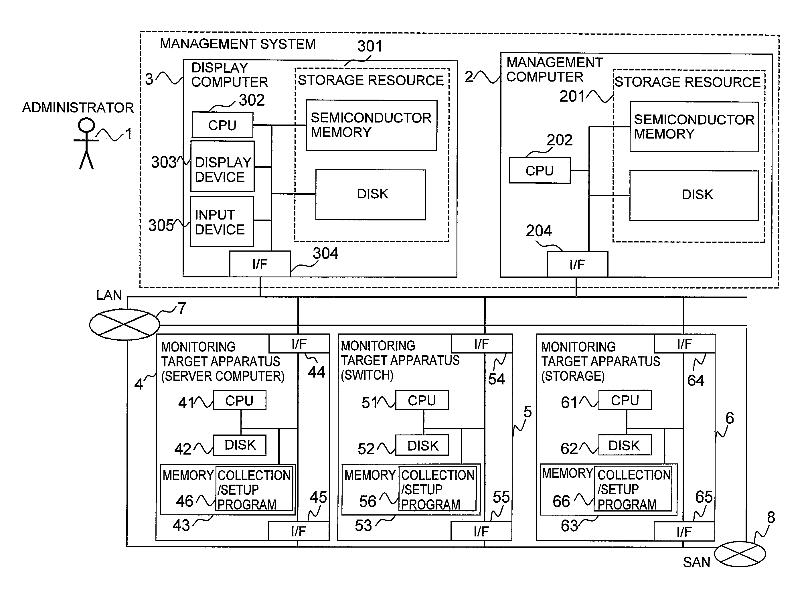
A management system, which manages multiple monitoring target apparatuses, computes a certainty factor denoting the probability that a certain configuration change is the root cause of a performance failure that has occurred in a certain monitoring target apparatus based on rule information, computer system performance information, and a configuration change history, and displays management information from the standpoint of the configuration change based on the computation result.

Description

TECHNICAL FIELD [0001]The present invention relates to a computer system, and more particularly to a method for avoiding a performance failure.BACKGROUND ART [0002]In recent years, computer systems, which comprise multiple apparatuses (for example, server computers, network apparatuses (switches, routers, and so forth), and storage apparatuses), form complex dependency relationships in which network services provided by the respective apparatuses are used by the other apparatuses, making management difficult.[0003]Patent Literature 1 discloses technology in which a management computer detects failures and other such events that occur in multiple apparatuses by monitoring the multiple apparatuses comprising the computer system, and possesses a RCA (Root Cause Analysis) function for inferring the root cause of an event that has occurred. Furthermore, the management computer of this Patent Literature comprises rule information, which, in order to perform this processing, includes one o...

Claims


Application Information

Patent Timeline
Patent Type & Authority Applications(United States)
IPC IPC(8): G06F15/173
CPCG06F11/0709G06F11/079G06F11/3495G06F11/3476G06F11/328
Inventor FUKUDA, SATOSHIBENIYAMA, NOBUOSATOMI, MITSUNORI
Owner HITACHI LTD
Learn More