Instrument kit for performing spinal stabilization

a technology for spinal stabilization and instruments, applied in the direction of bandages, applications, osteosynthesis devices, etc., can solve the problems of not proposing a technical solution for the design and production of instruments subjected to high mechanical stresses, unable to perform surgical interventions, and not being able to afford to own the operation

Active Publication Date: 2012-02-09
SAFE ORTHOPAEDICS SAS
View PDF7 Cites 68 Cited by
  • Summary
  • Abstract
  • Description
  • Claims
  • Application Information

AI Technical Summary

Benefits of technology

[0021]This solution makes it possible to disconnect the screw and withdraw the tube after the implantation of the screw without the need for a radial space to be available around the proximal end. This release is effected by spreading the distal ends of the tube apart, which is possible with the device according to the invention by pivoting each of the rigid half-shells with respect to the zone of fastening of the head of the screw. This spreading apart of the distal end also makes it possible to clear the view of the proximal zone of placement of the screw.

Problems solved by technology

Besides the disadvantage of providing only a single diameter and length of screw for the bone anchoring, this application describes only a single type of instrument, a screwdriver bar and its handle.
This international application does not propose a technical solution for the design and production of instruments subjected to high mechanical stresses.
Consequently, this sterile kit on its own does not allow a surgical intervention to be performed without also using traditional instruments, requiring re-sterilization after each intervention.
The reason is that it is difficult to reconcile the constraints of low production costs, a necessary condition for disposable instruments, and the qualities of mechanical strength, a necessary condition for instruments subjected to high stresses during their use by the surgeon.
The solutions in the prior art proposing that the screw be released by spreading apart the proximal ends of the screw-supporting tube are not satisfactory since they require a sufficient space in the zone surrounding the screw in order to permit disconnection.
However, in this zone, the presence of the bone part often limits the available space and may lead to difficulties in releasing the tube from the head of the screw.
Moreover, the forces that need to be transmitted for radially disengaging the proximal end of the tube from the head of the screw are substantial and involve maneuvers that are not especially ergonomic at a distance.
The release of the screw involves actions that can also lead to the operating site being concealed during this delicate phase of the intervention.
This retractor from the prior art poses a risk of unintentional rupturing of the weakened zone when a force is applied to the two flexible branches in order to spread the tissues apart.
The compromise between the flexibility allowing the two branches to be spread apart at an angle and the required rupture for withdrawing the instrument is delicate.
If the weakened zone is too strong, the surgeon may certainly apply considerable forces to the margins of the incision, but he will have to apply excessive and sometimes invasive forces when disconnecting the retractor from the screw.
If it is not strong enough, the surgeon risks breaking the retractor inadvertently during the intervention.
Moreover, this device does not allow the whole surgical intervention to be performed, and in particular it does not provide the instrumentation for placement of the rod, and then of the element for blocking the rod on the pedicle screw.

Method used


Image

  • Instrument kit for performing spinal stabilization
  • Instrument kit for performing spinal stabilization
  • Instrument kit for performing spinal stabilization

Examples


Embodiment Construction

)

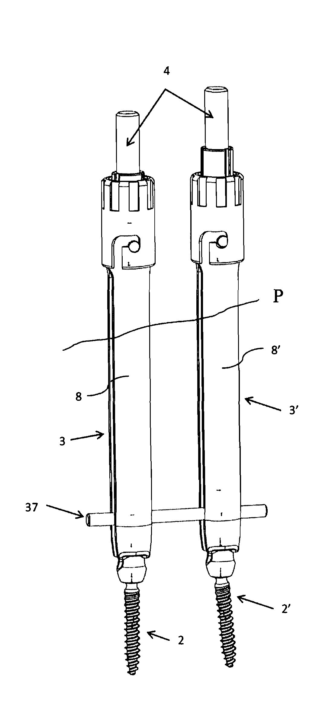
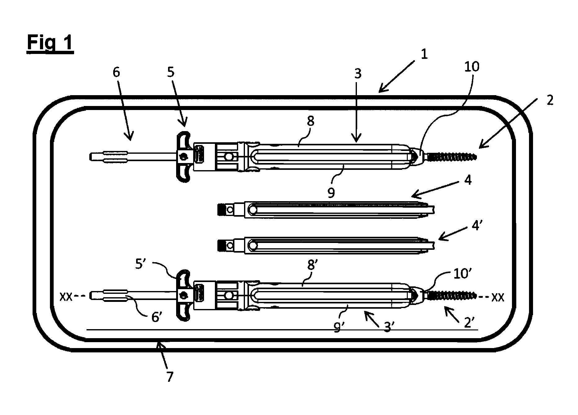
[0047]FIG. 1 describes a kit (1) for performing a surgical intervention for spinal stabilization. The kit (1) comprises:[0048]two screws (2, 2′) pre-mounted securely on assembly tubes (3, 3′),[0049]two securing elements (4, 4′) designed for placing the connecting rod on the bone-anchoring element and comprising blocking elements (41) pre-mounted on said securing tubes (3, 3′). The securing tubes (3, 3′) comprise a pre-mounted holding wing (5, 5′) and pre-mounted screwdriver (6, 6′).

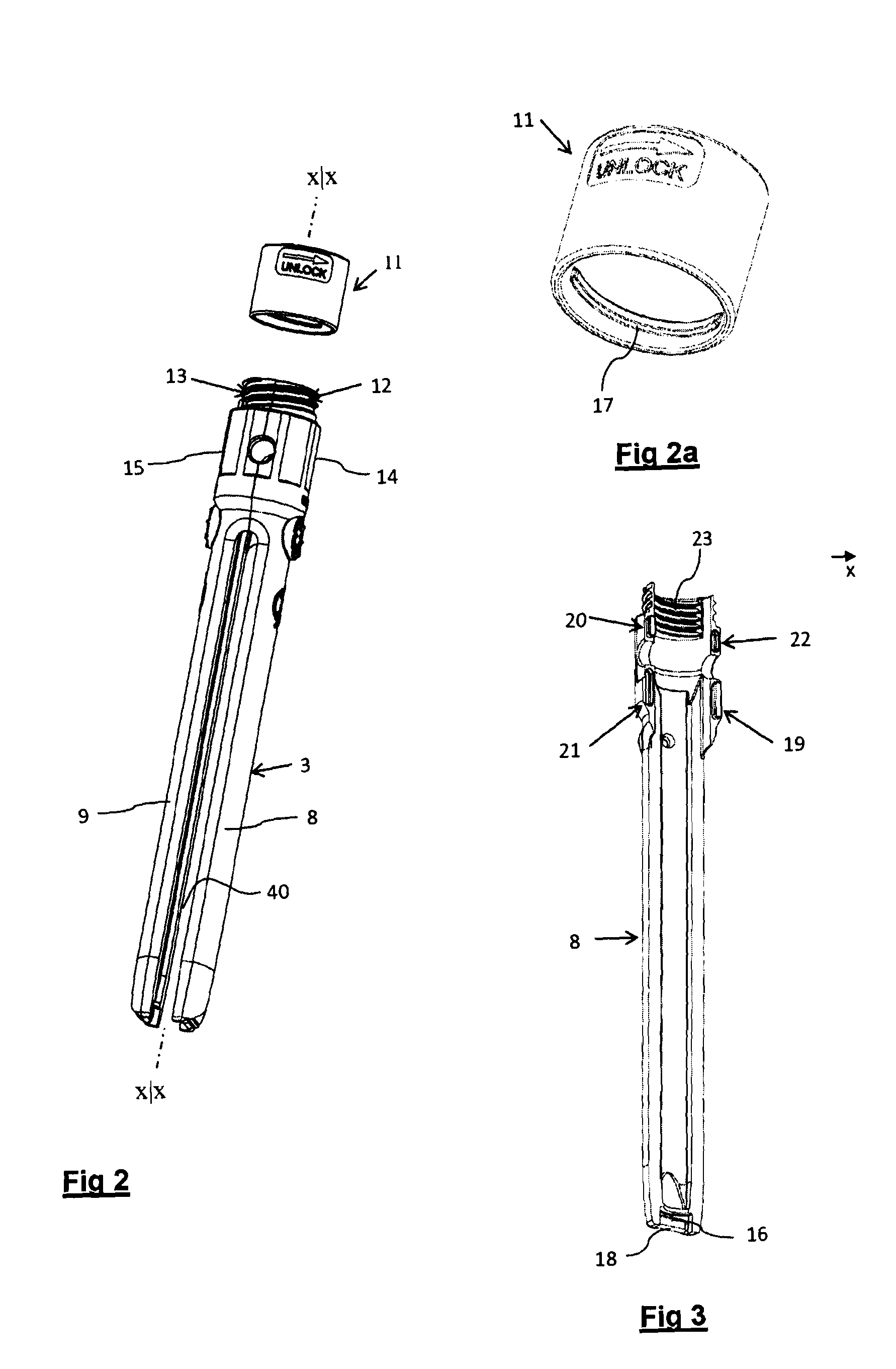
[0050]The assembly tube (3, 3′) is composed of two half-shells (8, 9) of semi-tubular section and of complementary shapes. The screw (2, 2′) is fastened to the proximal end of the two half-shells (8, 9; 8′, 9′) by virtue of an arrangement described below.

[0051]The securing element (4) is composed of a hollow rigid component that can be slid inside an assembly tube (3, 3′). It has an outer cross section complementing the inner cross section of the assembly tube (3, 3′). When the securing element (4, 4′) i...


PUM


Abstract

A disposable surgical kit for fixing the vertebrae using a posterior or postero-lateral route has at least one pedicle screw or vertebral screw and an assembly tube cooperating with the screw. The assembly tube is composed of two independent rigid half-shells. Each of the half-shells has, on the inner face of its proximal end, a shoulder with a shape complementing a recess formed on each side of the screw head in order to permit the gripping or the release of the screw by spreading apart the distal ends of the half-shells The kit additionally has a retractable securing element for securing the half-shells. The retractable securing element has longitudinal fastening means designed as a dovetail for engaging with complementary slides formed in the rigid half-shells.

Description

BACKGROUND[0001]1. Field of the Invention[0002]The invention relates to an instrument kit for performing spinal stabilization by means of a bone-anchoring element of the screw type and using posterior or postero-lateral routes.[0003]The instrument kit according to the invention is intended particularly, but not exclusively, for posterior surgical osteosynthesis of the lumbar, thoracic or even cervical spine, using minimally invasive routes or open surgery.[0004]In cases of anatomical dysfunction of the vertebral column, bone anchors in the form of pedicle screws or vertebral screws are placed in the vertebrae, which are connected to each other by rod-type or plate-type connecting elements.[0005]More particularly, the invention relates to the field of disposable instrument kits packed in a sterile state and comprising all the tools necessary for performing a surgical intervention for inserting pedicle screws without recourse to additional instruments.[0006]2. Prior Art[0007]The inter...

Claims


Application Information

Patent Timeline
Patent Type & Authority Applications(United States)
IPC IPC(8): A61B17/70A61B19/02
CPCA61B17/708A61B17/7076A61B19/0271A61B19/026A61B2019/0278A61B17/7082A61B50/30A61B50/33A61B2050/3008
Inventor PETIT, DOMINIQUE
Owner SAFE ORTHOPAEDICS SAS
Why Eureka
Try Eureka