Control system

Active Publication Date: 2012-02-09
AIRBUS HELICOPTERS DEUT GMBH
View PDF6 Cites 11 Cited by
  • Summary
  • Abstract
  • Description
  • Claims
  • Application Information

AI Technical Summary

Benefits of technology

[0038]redundant power supplies: higher availability of force amplification function, and
[0039]redundant linear actuators: higher availability of force amplification function.
[0040]According to a further preferred embodiment of the invention the duplex electric power supply and the force switch are parallel while the duplex controllable, electromechanical actuators, the duplex electric position sensors and the duplex actuator control electronics are in line respectively for improved reliability of the inventive control system. The probability of mechanical failure of the electromechanical actuators or the duplex electric position sensors is considered to be <10−7 compared to <10−4 for the probability of electric failure of the electromechanical actuators or the duplex electric position sensors.
[0041]According to a preferred embodiment of the invention a method of operating a control system comprises the following steps: a) inputting a command from the pilot or an autopilot actuator via the mechanical command input to move a mechanical linkage of a lever, a command shaft and an output shaft, b) deflecting the shaft of the electric position sensor in a proportional relationship to positioning error consisting of said mechanical command input and actuator output motion, c) providing electric current from a power source to the actuator control electronics, d) controlling said electric current by means of the actuator control electronics in response to the electric signal created by the electric position sensor, i. e. in a proportional relationship with the mechanical positioning error, for creating an electric signal responsive of the amplitude and the speed of said mechanical command input, and e) supplying the controlled current to the actuator for driving the output shaft in a direction to reduce the positioning error in terms of difference between the pilot's input command and the deflection of the actuator output shaft at the electric position sensor towards zero.
[0042]Accor

Problems solved by technology

The mechanical gear arrangements of document US 2004251061 (A1), namely the differential actuators imply an inherent risk of jamming.
The usage of gearboxes brings important issues concerning the reliability.
To apply such architecture to aerospace, the only solution would be to bring mechanical redundancies within the actuators and thus increase weight and complexity.
Therefore this state of the art in automotive industry is not suitable for a helicopter.
In the event of malfunction with the pilot command usually 3

Method used


Image

  • Control system
  • Control system
  • Control system

Examples


first embodiment

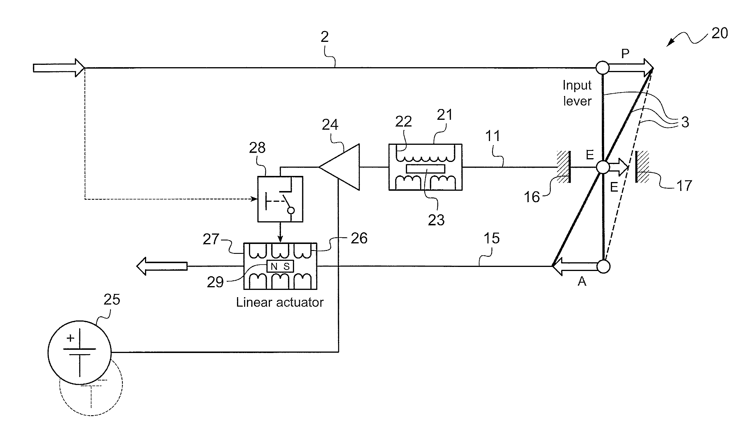
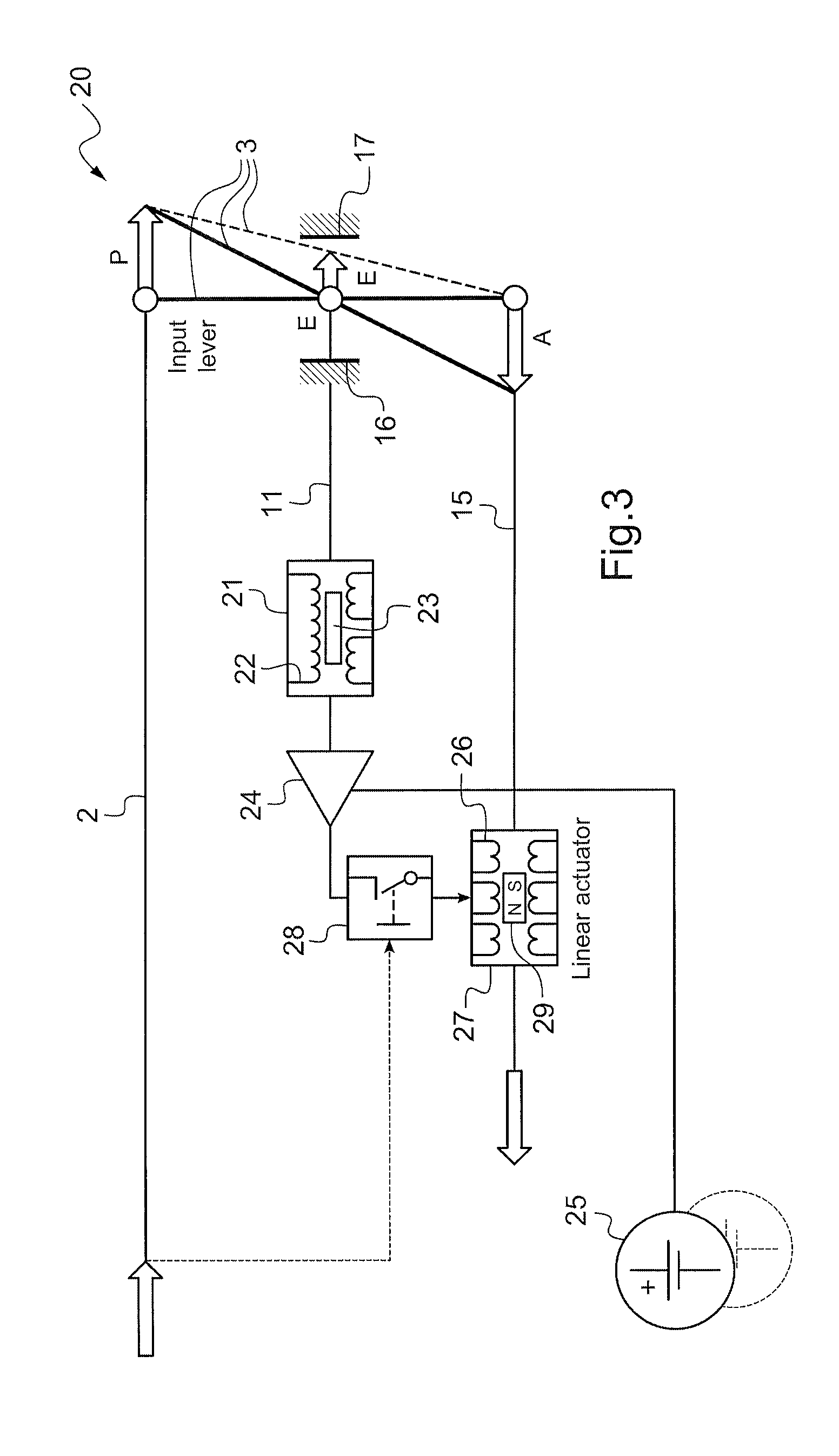
[0063]FIG. 3: Corresponding features are referred to by the same references as in FIG. 1, 2. the control system 20 of pilot command inputs for a small or medium helicopter is provided with a mechanical input 2 for linear transmission of said pilot command inputs with an input linear force in the range of approximately 10 N to up to 500 N to a lever 3 of a mechanical linkage. Lever 3 is shown in a vertical, neutral position, in an intermediate actuated position in a dotted line and in an inclined actuated position. A command shaft 11 is fixed to an intermediate joint of the lever 3 and mechanically linked to an electric position sensor 21 of said input command. Linkage stops 16, 17 are provided on either side of the intermediate joint at the lever 3 to limit the stroke of the command shaft 11.

[0064]The electric position sensor 21 is provided with an electric solenoid 22 arranged around an induction core 23 inducing to the electric solenoid 22 an electric current representative of dis...

second embodiment

[0076]FIG. 7: Corresponding features are referred to by the same references as in FIG. 1-6. a control system 40 corresponds essentially to the control system of FIG. 3 apart from the arrangement of the force switch 28 said force switch 28 being electrically controlled by the pilot's input commands activating the force switch 28 to interrupt the electric power supply 25 to the actuator control electronics 24 after detection that a predetermined force threshold of a pilot's command has been passed in order to prevent loss of control in cases of electric failures, especially powered run-away failures.

third embodiment

[0077]FIG. 8: Corresponding features are referred to by the same references as in FIG. 1-7. a control system 50 corresponds essentially to the control system of FIG. 7 apart from the arrangement of the output shaft 15 of the electromechanical actuator 27 being linked to the intermediate joint at the lever 3 and the command shaft 11 to the electric position sensor 21 being mounted to the end of the lever 3 opposite to the command's input.

[0078]FIG. 9, 10: Corresponding features are referred to by the same references as in FIG. 1-8. The control system 50 of FIG. 8 is provided with a supplemental safety device 51 mounted next to the command shaft 11 to the electric position sensor 21 at the end of the lever 3 opposite to the command's input.

[0079]The supplemental safety device 51 comprises a sloppy lock 52 for the joint of the lever 3 to the command shaft 11. The sloppy lock 52 is movable between a position distant from the command shaft 11 and a locking position for the command shaft ...


PUM


Abstract

The invention relates to a control system and to a method of operating such a control system, particularly to a control system for pilot command inputs for a helicopter, with a mechanical input signal (2), at least one electric position sensor (21, 21′) for said input signal (2), at least one electric power supply (25, 25′) and at least one controllable, electromechanical actuator (27, 27′) fed by the at least one electric power supply (25, 25′) and controlled by the at least one electric position sensor (21, 21′). The mechanical input signal (2) is applied mechanically to the at least one controllable electromechanical actuator (27, 27′).

Description

CROSS REFERENCE TO RELATED APPLICATION[0001]The present application claims priority benefit from European patent application EP 10 400037.7 of Aug. 4, 2010, the content of which is incorporated herein by reference.FIELD OF THE INVENTION[0002]The invention relates to a control system, particularly to a control system for pilot command inputs for a rotorcraft, notably a helicopter with the features of the preamble of claim 1 and to a method of operating such a control system.BACKGROUND OF THE INVENTION[0003](1) Field of the Invention[0004]To control a helicopter, in general via the main rotor or tail rotor, the pilot has to send a command which moves the rotor blades. In case of installed servo systems either for comfort purposes or for necessary force amplification due to high air loads, the pilot command will activate an actuator motion.[0005]There are two classical methods for the actuator power generation, electric or hydraulic. The hydraulic method needs a complex system of reser...

Claims


Application Information

Patent Timeline
IPC IPC(8): B64C13/04
CPCB64C27/56B64C13/42
Inventor GROHMANN, BORISPAULMANN, GREGOR
Owner AIRBUS HELICOPTERS DEUT GMBH
Why Eureka
Try Eureka