Wind turbine generator
- Summary
- Abstract
- Description
- Claims
- Application Information
AI Technical Summary
Benefits of technology
Problems solved by technology
Method used
Image

Examples
first embodiment
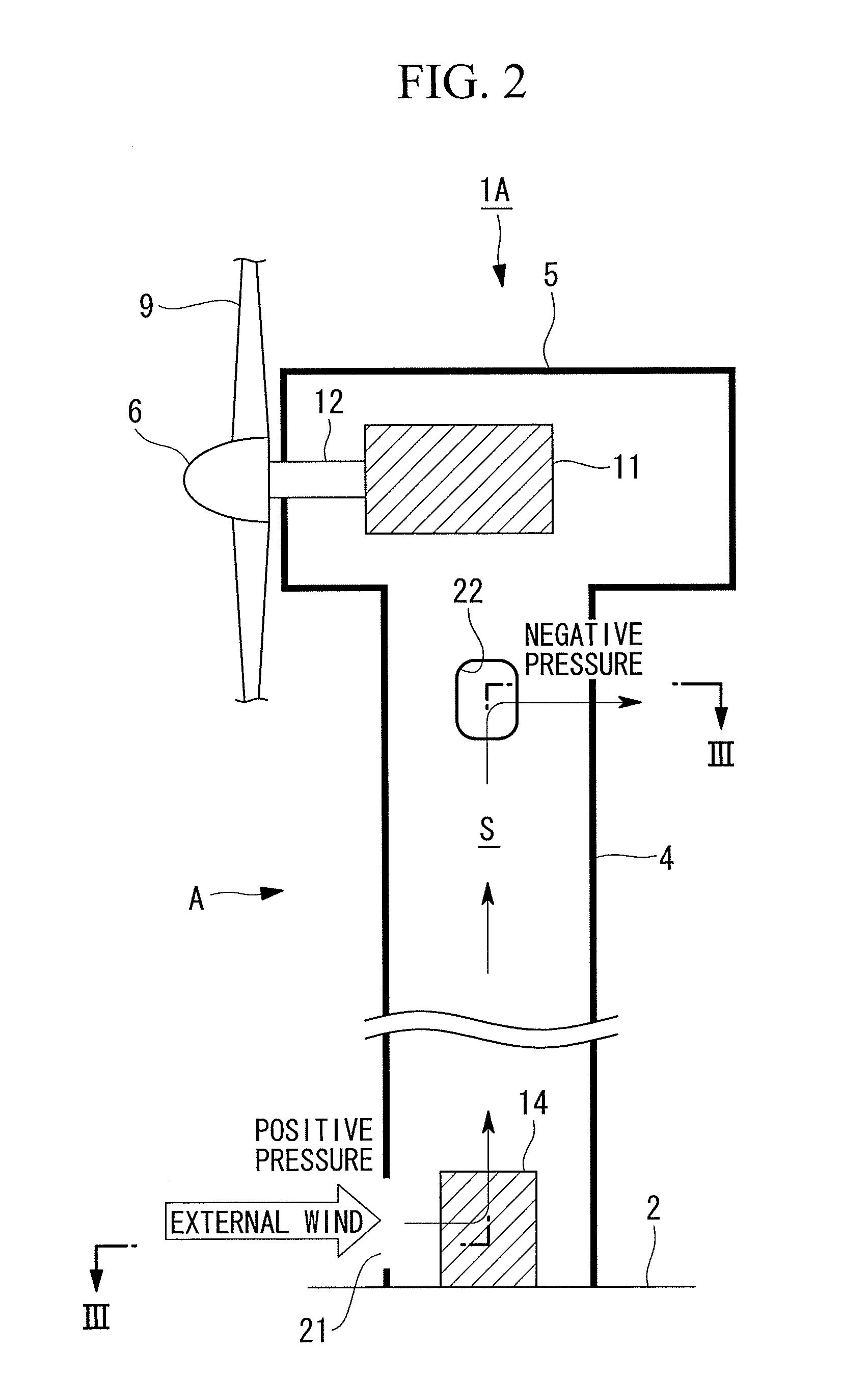
[0073]FIG. 2 is a schematic longitudinal cross-section of a wind turbine generator 1A according to a first embodiment of the present invention, and FIG. 3 is a lateral cross-section taken along line III-III in FIG. 2. The wind turbine generator 1A is provided with a cooling structure A. In this cooling structure A, an introducing vent 21 and an exhaust vent 22 are provided in the tower 4 having a substantially circular cross-sectional shape as described above. The introducing vent 21 is an opening for taking external wind into the internal space S in the tower 4 as cooling air and is provided at an outer circumference surface of the tower 4 at a portion that receives positive pressure due to the external wind. The exhaust vent 22 is an opening for externally exhausting the cooling air inside the internal space S and is provided at the outer circumference surface of the tower 4 at a portion that receives negative pressure due to the external wind.
[0074]More specifically, in considera...
second embodiment
[0082]FIG. 5 is a schematic longitudinal cross-section of a wind turbine generator 1B according to a second embodiment of the present invention. The wind turbine generator 1B is provided with a cooling structure B. This cooling structure B differs from the cooling structure A in the above-described first embodiment only in that the installation height of the introducing vent 21 is close to a middle portion of the tower 4 and that the installation height of the exhaust vent 22 is close to the bottom end of the tower 4, and other configurations are the same as those of the cooling structure A. That is, the positional relationship between the introducing vent 21 and the exhaust vent 22 in plan view is as shown in FIG. 3, and operational advantages brought about by doing so are also similar to those of the cooling structure A.
[0083]In this cooling structure B, the height of the introducing vent 21 is set near the highest position in a range R from the ground surface 2 to a bottom end of...
third embodiment
[0085]FIG. 6 is a schematic longitudinal cross-section of a wind turbine generator 1C according to a third embodiment of the present invention, FIG. 7 is a lateral cross-section taken along line VII-VII in FIG. 6, and FIG. 8 is a lateral cross-section taken along line VIII-VIII in FIG. 6. The wind turbine generator 1C is provided with a cooling structure C. In this cooling structure C, as in the cooling structure A in the first embodiment, the introducing vent 21 is disposed near the bottom end of the tower 4, and exhaust vents 22a to 22d are disposed near the top end of the tower 4.
[0086]As in the cooling structure A, in the circumference direction of the outer circumference surface of the tower 4, the introducing vent 21 is provided only at a single location at a surface where the wind strikes the most on average throughout the year, that is, the surface subjected to the highest positive pressure due to the external wind. On the other hand, the exhaust vents 22a to 22d are provide...
PUM
 Abstract
Description
Claims
Application Information
 - R&D
- Intellectual Property
- Life Sciences
- Materials
- Tech Scout
- Unparalleled Data Quality
- Higher Quality Content
- 60% Fewer Hallucinations
Browse by: Latest US Patents, China's latest patents, Technical Efficacy Thesaurus, Application Domain, Technology Topic, Popular Technical Reports.
© 2025 PatSnap. All rights reserved.Legal|Privacy policy|Modern Slavery Act Transparency Statement|Sitemap|About US| Contact US: help@patsnap.com