
Coil bobbin for superconducting magnetic energy storage

a superconducting magnetic and coil technology, applied in the direction of superconducting magnets/coils, magnets, magnetic bodies, etc., can solve the problems of increasing the vertical magnetic field on the conductive portions, reducing the operating current of the superconducting magnet eventually, etc., and achieve the effect of reducing the magnitude of the vertical magnetic field

Active Publication Date: 2012-02-09
KOREA ELECTROTECH RES INST
View PDF6 Cites 8 Cited by
  • Summary
  • Abstract
  • Description
  • Claims
  • Application Information

AI Technical Summary

Benefits of technology

[0009]Accordingly, the present invention has been made keeping in mind the above problems occurring in the prior art, and an object of the present invention is to provide a coil bobbin for a superconducting magnetic energy storage which can reduce the magnitude of a vertical magnetic field generated by the superconducting coil.
[0026]A coil bobbin for a superconducting magnetic energy storage according to the present invention can reduce the magnitude of a vertical magnetic field generated by the superconducting coil.
[0027]Furthermore, the present invention can reduce an eddy current loss which is caused when the superconducting magnetic energy storage is operated.
[0028]In addition, the present invention can increase the efficiency of cooling superconducting coils.

Problems solved by technology

As the magnitude of the vertical magnetic field increases, the critical current is reduced, resulting in the problem of the operating current of the superconducting magnet eventually being reduced.
That is, there is the problem of an increase in the vertical magnetic field on the conductive portions that are displaced from the curved surface of the toroidal structure.

Method used


Image

  • Coil bobbin for superconducting magnetic energy storage
  • Coil bobbin for superconducting magnetic energy storage
  • Coil bobbin for superconducting magnetic energy storage

Examples


Embodiment Construction

[0057]Hereinafter, the present invention will be described in detail with reference to the attached drawings.

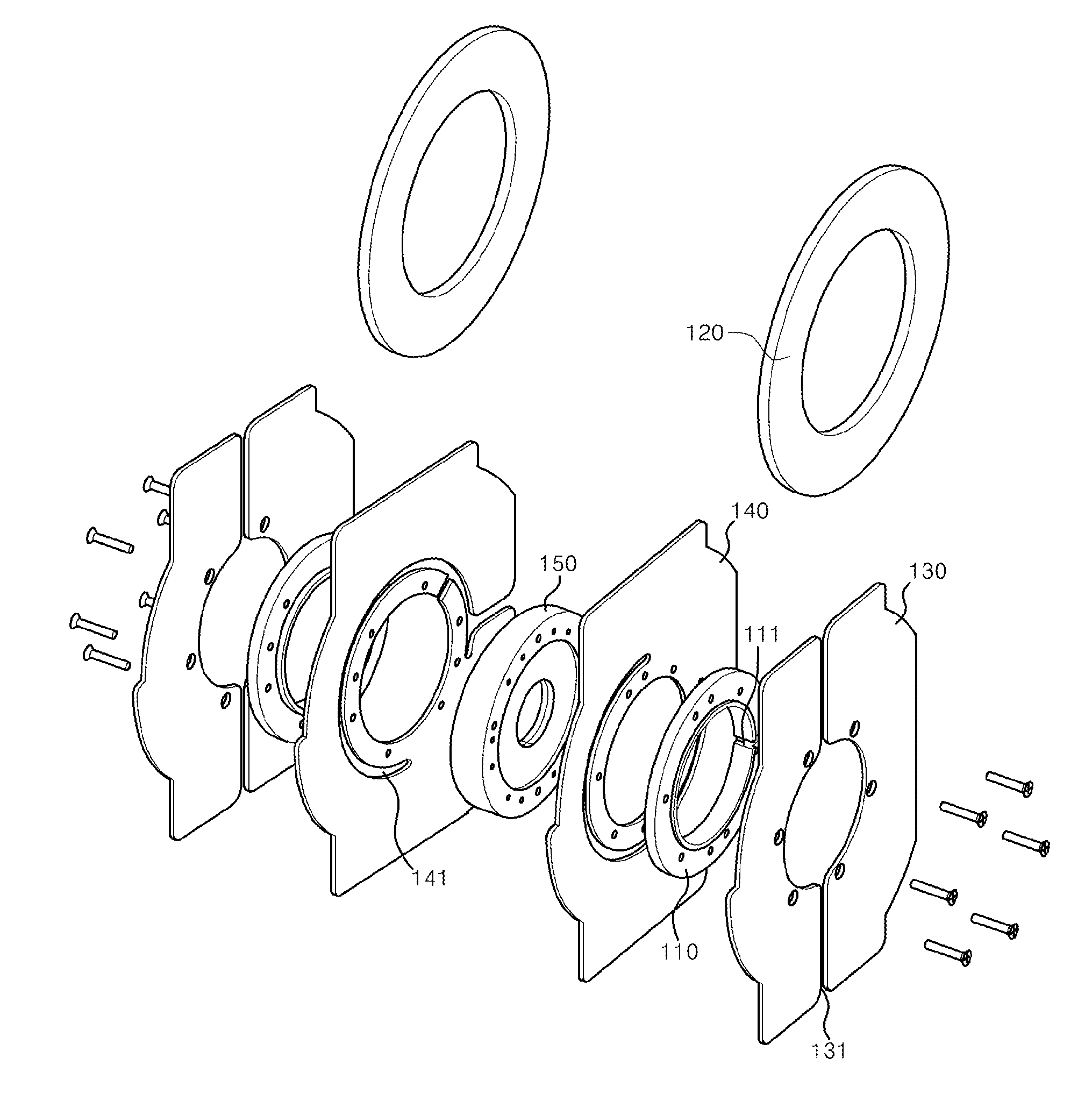
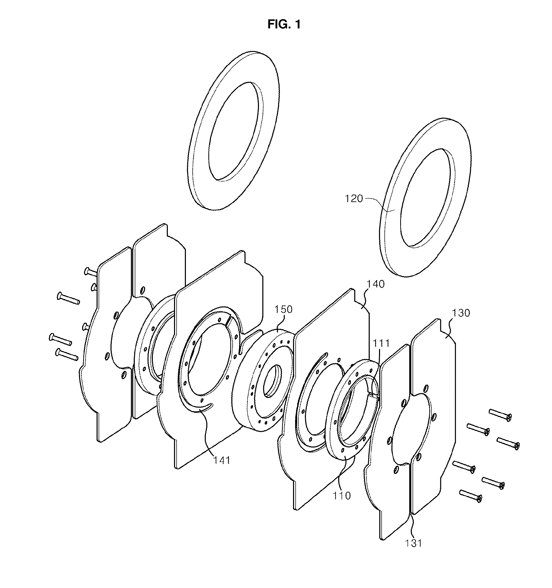
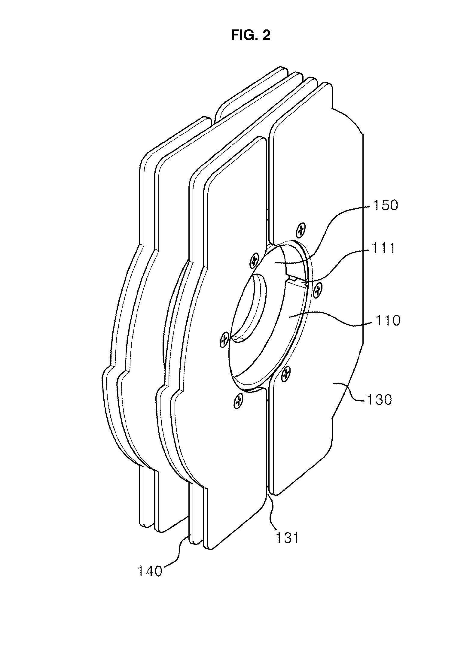
[0058]FIGS. 1 and 2 are views illustrating a coil bobbin for a superconducting magnetic energy storage, according to an embodiment of the present invention. In detail, FIG. 1 is an exploded perspective view of the coil bobbin for the superconducting magnetic energy storage, according to the embodiment of the present invention. FIG. 2 is a perspective view of the assembled coil bobbin for the superconducting magnetic energy storage according to the embodiment of the present invention.

[0059]As shown in FIGS. 1 and 2, the coil bobbin for the superconducting magnetic energy storage according to the embodiment of the present invention includes coil bobbin frames 110, superconducting coils 120, first support plates 130, second support plates 140 and a center frame 150.

[0060]The coil bobbin frames 110 have annular plate shapes, around which the superconducting coils 120 are wound. I...


PUM


Abstract

Disclosed herein is a coil bobbin for a superconducting magnetic energy storage. The coil bobbin includes coil bobbin frames, superconducting coils, first support plates, second support plates and a center frame. The coil bobbin frames are provided in such a way as to face each other. The superconducting coils are wound around the respective coil bobbin frames. The first support plates are provided on surfaces of the respective coil bobbin frames that are on faces that are opposite to the surfaces between the coil bobbin frames that face each other. The second support plates are provided on the respective facing surfaces of the coil bobbin frames. The center frame is disposed between the second support plates and has an annular plate shape having a thickness that is gradually reduced towards a center of the toroidal arrangement.

Description

REFERENCE TO RELATED APPLICATIONS[0001]This is a continuation of pending International Patent Application PCT / KR2010 / 008406, filed on Dec. 1, 2010, which designates the United States and claims priority of Korean Patent Application No. 10-2010-0003046, filed on Jan. 13, 2010, the entire contents of which are incorporated herein by reference.FIELD OF THE INVENTION[0002]The present invention relates to a coil bobbin for a superconducting magnetic energy storage having a plurality of coil bobbins to allow a superconducting coil to be wound in a toroidal arrangement.BACKGROUND OF THE INVENTION[0003]Recently, with the advances society has made in technology and the expansion of information and communication equipment, computation equipment, online service equipment, automated production line and precise control equipment, there has been a lot of research into superconducting magnetic energy storage (SMESs) aiming to provide high-quality power to sensitive and important loads placed on eq...

Claims


Application Information

Patent Timeline
IPC IPC(8): H01F17/04
CPCH01F27/22H01F6/06
Inventor SOHN, MYUNGHWANBAE, JOONHANSEONG, KICHULSIM, KIDEOKKIM, HAEJONGKIM, HOMIN
Owner KOREA ELECTROTECH RES INST
Learn More