Fan with area expansion between rotor and stator blades

a technology of stator blades and rotors, which is applied in the direction of liquid fuel engines, marine propulsion, vessels, etc., can solve the problems of affecting the performance of electronic parts, and achieve the effects of increasing static pressure, and effective reducing the sound power level

Active Publication Date: 2012-02-09
MINEBEAMITSUMI INC
View PDF8 Cites 15 Cited by
  • Summary
  • Abstract
  • Description
  • Claims
  • Application Information

AI Technical Summary

Benefits of technology

[0003]Embodiments according to the present invention provide an axial-flow fan structure with localized area expansion between the rotor (i.e. front rotating impeller) and stator blades (i.e. rear stationary or fixed blades, sometimes called de-swirl vanes). In embodiments, the area expansion may utilize an impeller with a (slightly) falling tip contour (FTC), thus providing effective reduction of the sound power level (fan noise).
[0004]Embodiments of the present invention relate to an axial flow fan device. Specifically, certain embodiments relate to a small axial flow fan device used to exhaust heat generated by electronic parts inside a housing. More particularly, embodiments of the present invention relate to axial flow fans having an area expansion region between the rotor and stator blades to reduce the sound power level.
[0005]Embodiments of the present invention can increase static pressure and air flow, while at the same time decreasing sound power level (noise level) by controlling the airflow and preventing pressure loss during exhaust of the air. In embodiments, an axial flow fan can be reduced in size without having to reduce the circuit board that is used to control the axial flow fan and without obstructing air flow. In an embodiment, the circuit board for driving the fan motor can be disposed parallel to the axis of rotation. In an embodiment an axially disposed circuit board storage portion may be providing in the fan housing for receiving a circuit board for controlling the fan motor.
[0006]Embodiments of the present invention provide an axial flow fan having blade shapes which would allow a reduction of surface area of a fan inside its housing. In embodiments, such reduction in surface area may be provided around the trailing edges of the fan blades. Consequently, aerodynamic force exerted on the fan can be reduced. The inside of the fan housing may be narrowed along a trajectory line in the direction from a tip of the fan blade toward the rotational axis.

Problems solved by technology

The generated heat may possibly damage these electronic parts.

Method used


Image

  • Fan with area expansion between rotor and stator blades
  • Fan with area expansion between rotor and stator blades
  • Fan with area expansion between rotor and stator blades

Examples


Embodiment Construction

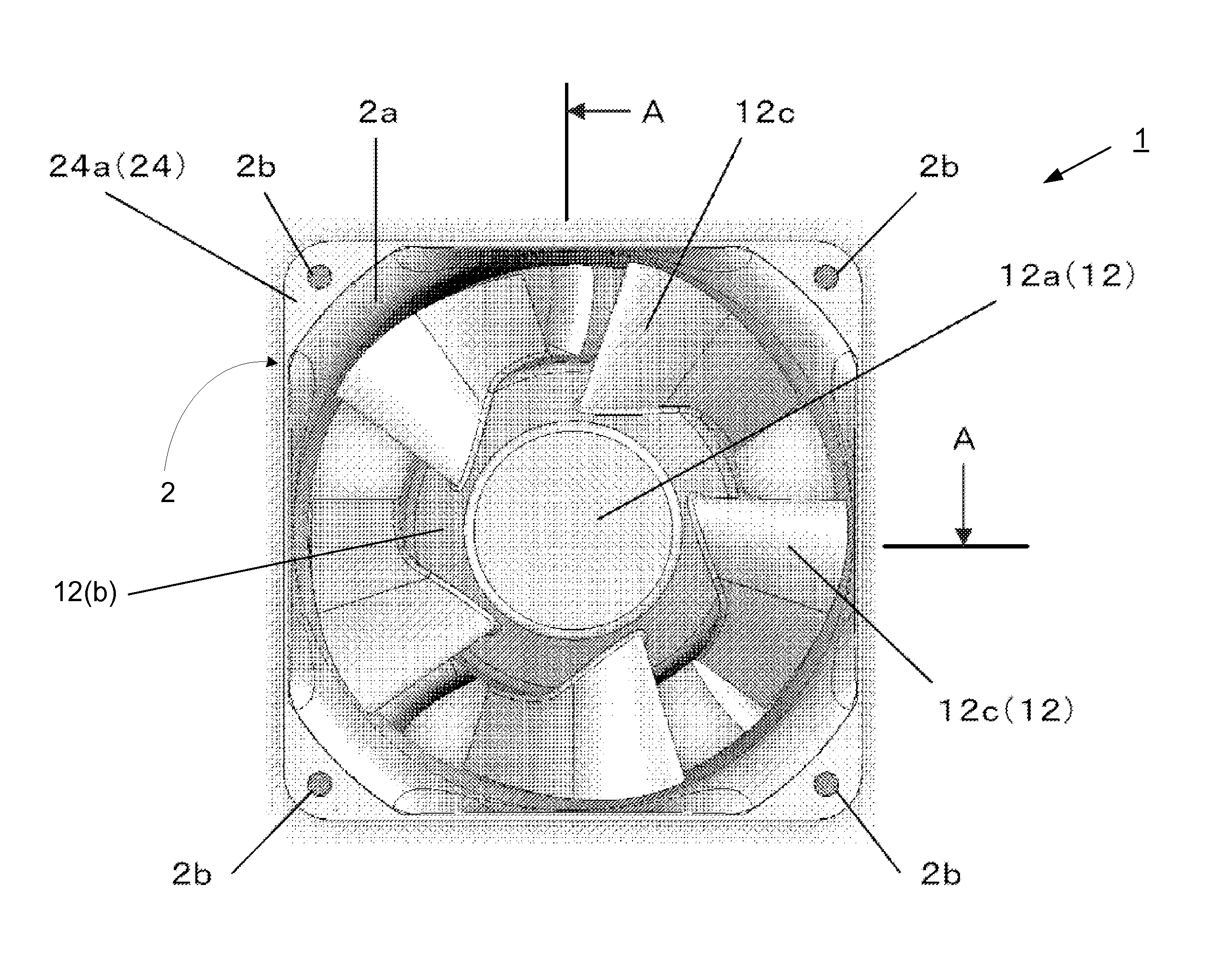
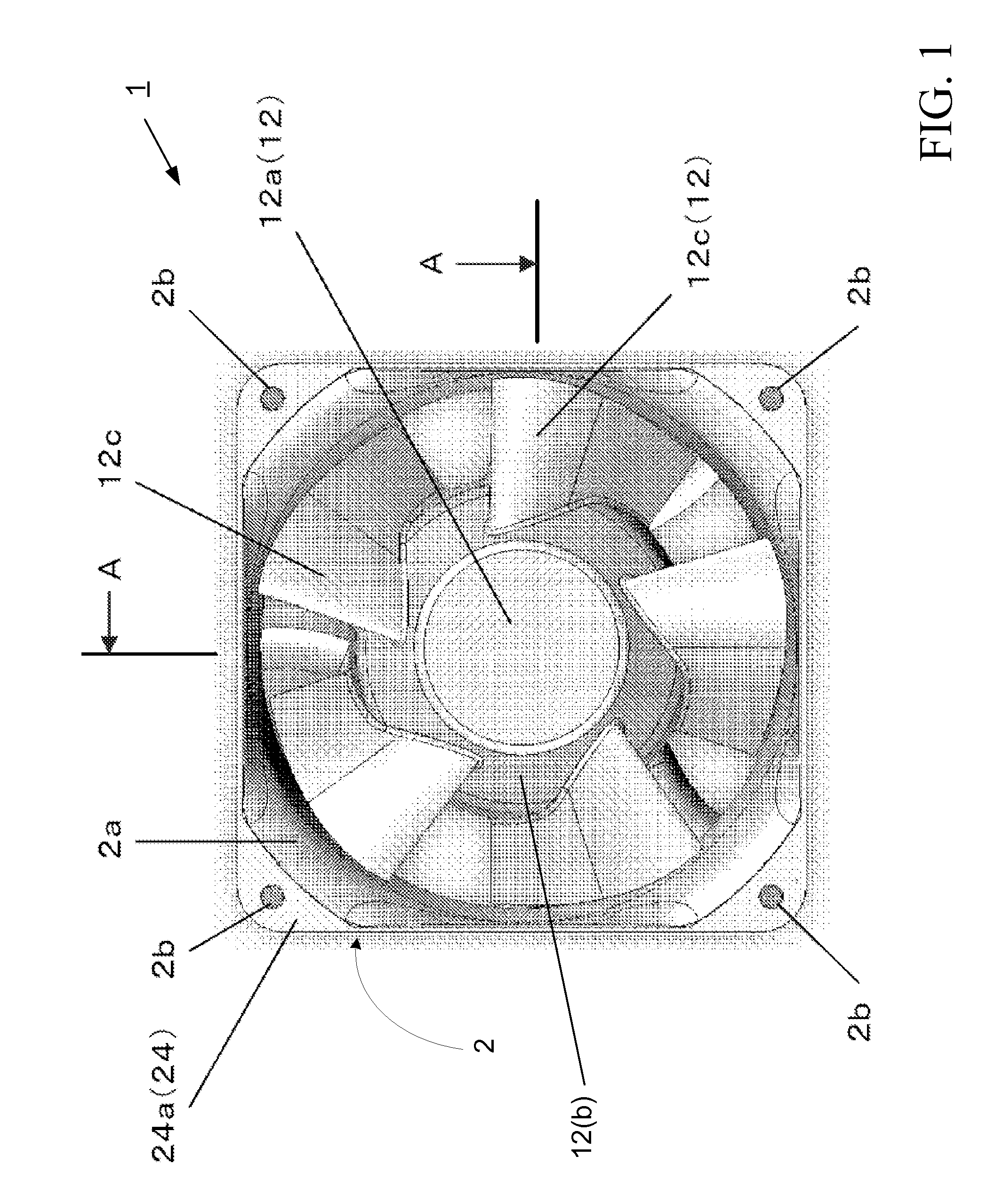
[0014]FIG. 1 illustrates a front-facing view of an embodiment of a fan 1 in accordance with the present invention. In embodiments, the fan 1 may be an axial flow fan. In embodiments, the fan may include a fan housing 2 having an impeller 12 disposed within the fan housing. The impeller 12 may comprise an impeller body 12a having fan blades 12c connected to a hub 12b. An air flow opening 2a may be formed in a central part of the fan housing 2. The fan housing 2 may include an inlet housing ring 24 having a flange 24a provided with installation through-holes 2b for installation in an electronic device to be cooled (not shown).

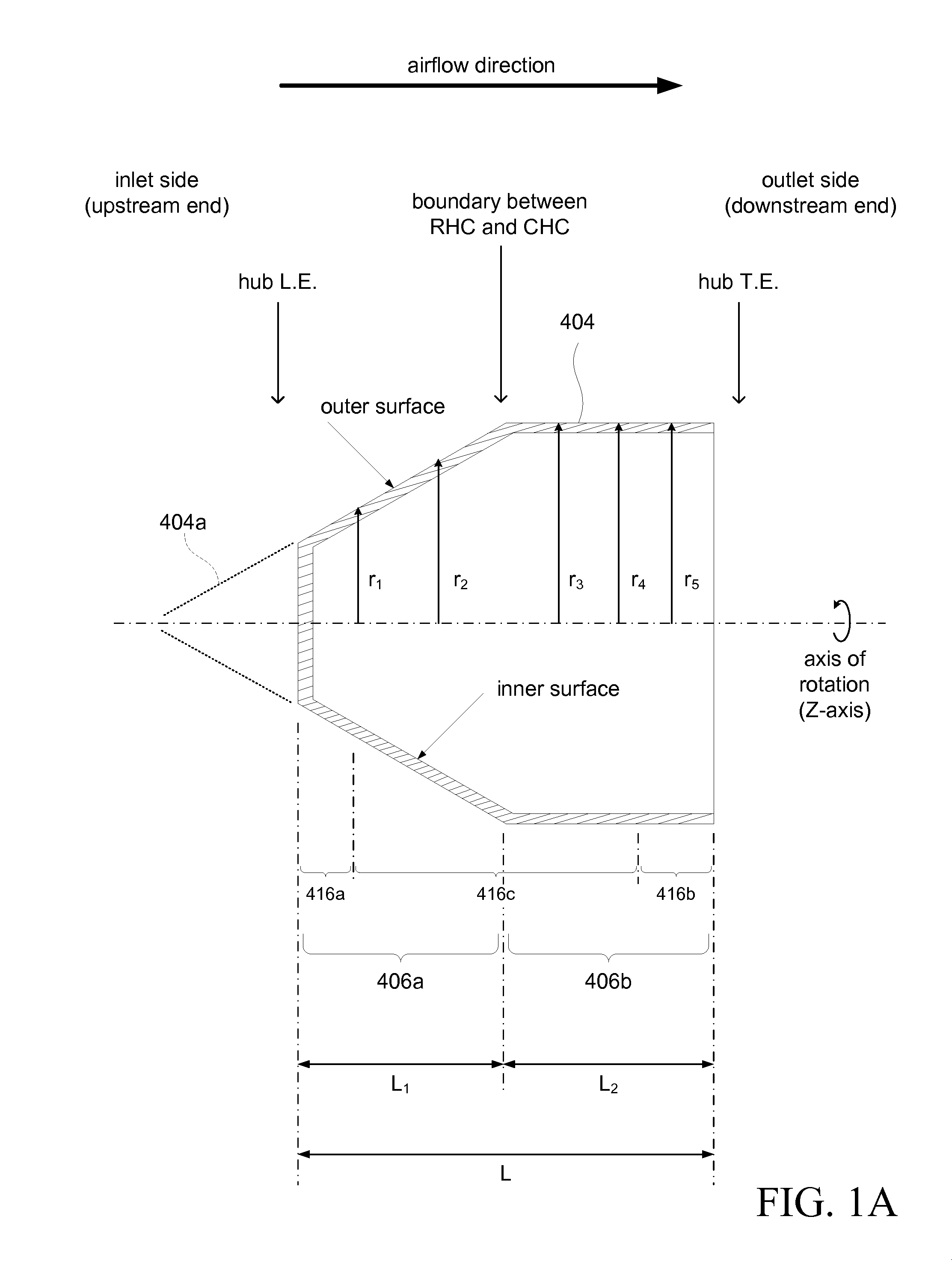
[0015]In an embodiment, the hub 12b may have a rising hub contour. This can be seen in the front-facing view of the impeller body 12a shown in FIG. 1. Referring for a moment to FIG. 1A, the rising hub contour can be seen in the cross-sectional view.

[0016]FIG. 1A shows a cross-sectional view of a hub 404 of an embodiment of the present invention. The figure is a d...


PUM


Abstract

An axial-flow fan structure is disclosed, having a localized area expansion between the rotor (i.e. front rotating impeller) and stator blades (i.e. rear stationary or fixed blades, sometimes called de-swirl vanes). The area expansion is provided by utilizing an impeller having a (slightly) falling tip contour (FTC).

Description

CROSS-REFERENCES TO RELATED APPLICATIONS[0001]This application claims priority to U.S. Provisional Application No. 61 / 371,243 filed Aug. 6, 2010 and is incorporated herein in its entirety for all purposes. This application is related to commonly owned U.S. application Ser. No. 12 / 629,699, filed Dec. 2, 2009 which is incorporated herein in its entirety for all purposes.BACKGROUND[0002]Modern electronic devices, for example, personal computers and copiers which enclose a large number of electronic parts inside a relatively small housing, tend to retain heat generated by these electronic parts. The generated heat may possibly damage these electronic parts. In order to prevent such damage, air through-holes are typically provided on side walls of the device housing and top surfaces of the housing. A fan installed near the air through-holes may then remove the heat that is generated inside the housing.BRIEF SUMMARY[0003]Embodiments according to the present invention provide an axial-flow...

Claims


Application Information

Patent Timeline
Patent Type & Authority Applications(United States)
IPC IPC(8): F01D5/22
CPCF04D25/0613F04D29/545F04D29/542
Inventor SHOJI, HIROFUMIJARRAH, YOUSEFWACKERLY, KEVIN
Owner MINEBEAMITSUMI INC
Why Eureka
Try Eureka