Idle stop vehicle and control method thereof

a technology of idling stop and control method, which is applied in the direction of electric control, engine starters, instruments, etc., can solve the problems of driver's incongruity sense and driver's incongruity sens

Active Publication Date: 2012-02-09
JATCO LTD
View PDF4 Cites 15 Cited by
  • Summary
  • Abstract
  • Description
  • Claims
  • Application Information

AI Technical Summary

Benefits of technology

[0009]According to another aspect of the present invention, a control method for a vehicle which performs an idle stop to automatically stop an engine during a stop of the vehicle is provided. The method includes determining whether or not an idle sto

Problems solved by technology

A timing at which the oil temperature of the transmission enters the temperature range where the idle stop is permitted cannot be actively controlled, with the result that a period until the idle stop condition holds and the engine automatically stops varies.
However, if the period until the engine automatically stops largely varies, a sense of incongruity is given to a driver.
Parti

Method used


Image

  • Idle stop vehicle and control method thereof
  • Idle stop vehicle and control method thereof
  • Idle stop vehicle and control method thereof

Examples


first embodiment

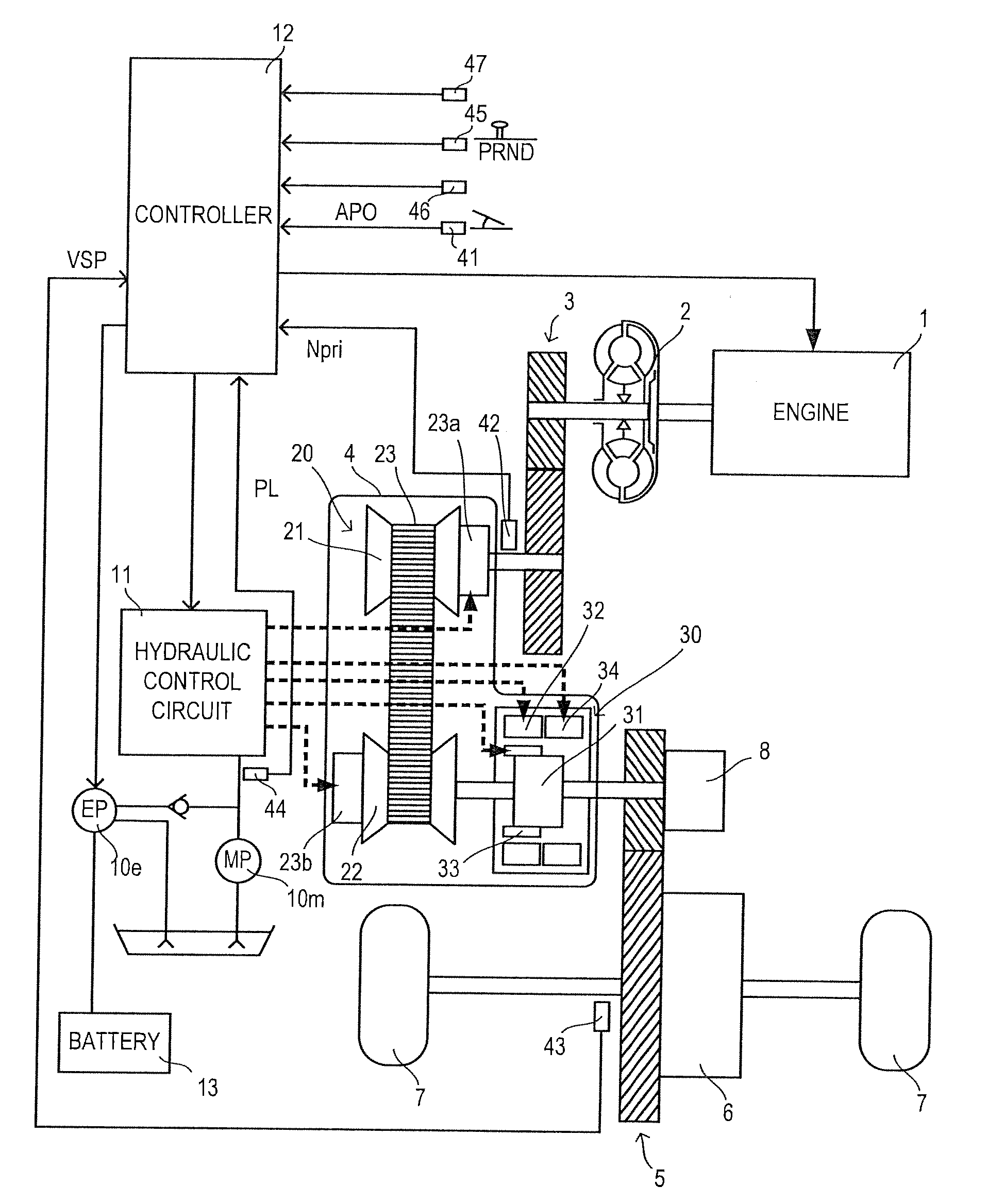
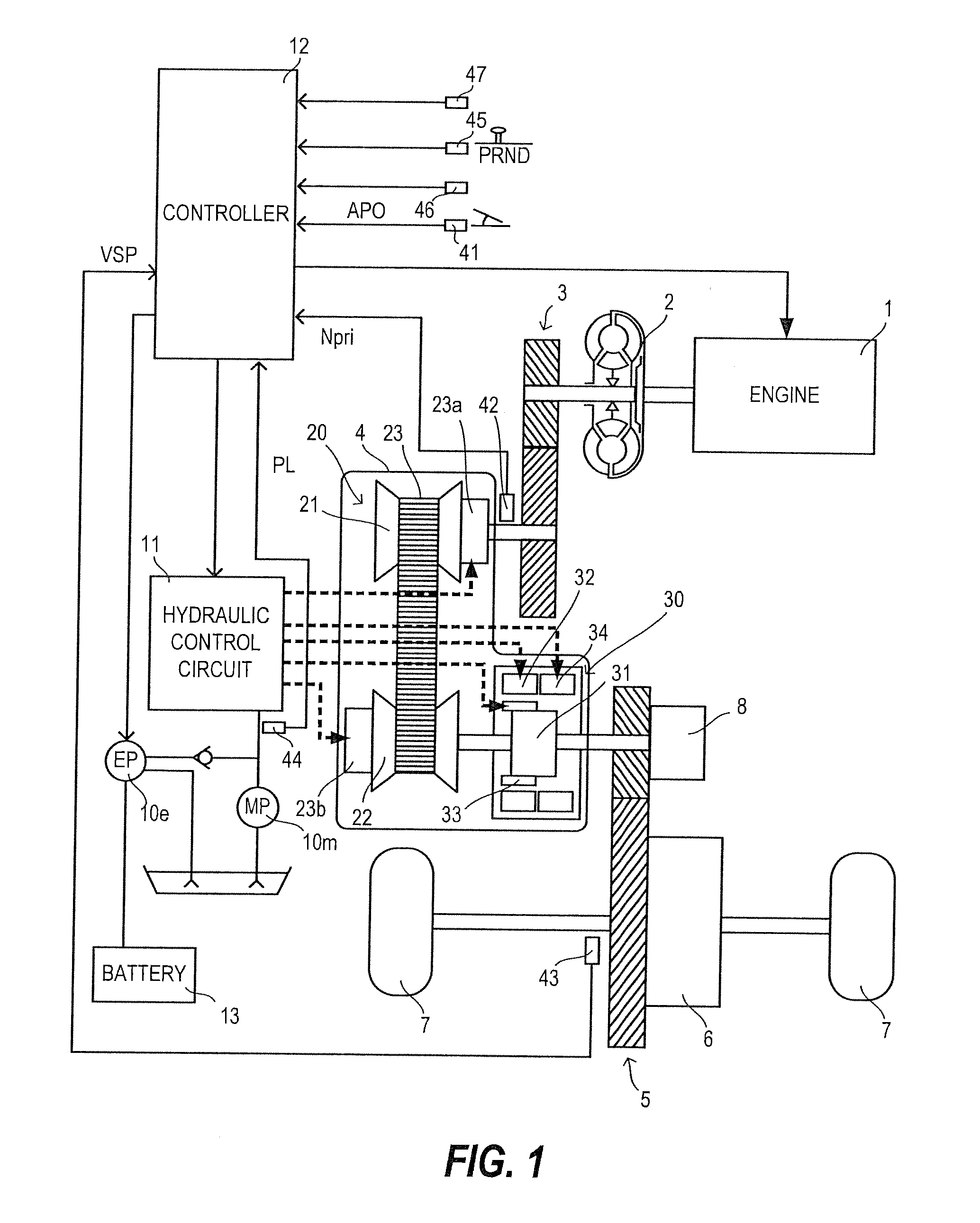
[0021]FIG. 1 is a schematic construction diagram of an idle stop vehicle according to the present invention. This vehicle includes an engine 1 as a driving source, and output rotation of the engine 1 is transmitted to drive wheels 7 via a torque converter 2 with a lock-up clutch, a first gear train 3, a continuously variable transmission (hereinafter, merely referred to as a “transmission 4”), a second gear train 5 and a final reduction unit 6. The second gear train 5 includes a parking mechanism 8 for mechanically locking an output shaft of the transmission 4 in a parked state so as not to be able to rotate.

[0022]The transmission 4 includes a mechanical oil pump 10m to which the rotation of the engine 1 is input and which is driven by utilizing a part of power of the engine 1 and an electrical oil pump 10e which is driven upon receiving the supply of power from a battery 13. The electrical oil pump 10e is composed of an oil pump main body and an electric motor and a motor driver fo...

second embodiment

[0071]Next, the present invention is described.

[0072]In the second embodiment, a neutral idle control (hereinafter, referred to as an “N idle control”) is performed under a predetermined condition in addition to the idle stop control to suppress a fuel consumption amount during a stop of a vehicle and further improve fuel economy. The overall construction of the vehicle is as in the first embodiment.

[0073]

[0074]The N idle control is a control for suppressing a fuel consumption amount by reducing a transmittable torque of a low brake 32 by reducing a hydraulic pressure supplied to the low brake 32, which is a frictional engagement element for start, to a hydraulic pressure at which the low brake 32 is almost engaged (state where facing engaging members constituting the low brake 32 are slightly in contact or in a state immediately before coming into contact) to reduce loads of an engine 1 and a mechanical oil pump 10m during a stop of the vehicle. Although an example in which the hyd...

third embodiment

[0108]Next, the present invention is described.

[0109]In the second embodiment, the N idle control is not performed until the specified time TLIM elapses even when the N idle condition holds before the stoppage time exceeds the specified time TLIM for the purpose of avoiding a shock when the state is switched from the N idle state to the idle stop state. On the contrary, in the third embodiment, by prioritizing an improvement in fuel economy over shock prevention, the N idle control is immediately performed when the N idle condition holds. Thereafter, if the idle stop condition holds before the stoppage time exceeds the specified time TLIM, the N idle state is switched to the idle stop state at that timing.

[0110]Other points such as the overall construction of a vehicle, the prohibition of the idle stop when the stoppage time exceeds the specified time TLIM without the idle stop condition holding and the performance of the N idle control when the N idle condition holds after the stop...


PUM


Abstract

An idle stop vehicle performs an idle stop to automatically stop an engine during a stop of the vehicle. The vehicle includes an idle stop condition determination unit for determining whether or not an idle stop condition holds, and an engine control unit for performing the idle stop when the idle stop condition holds before a stoppage time exceeds a specified time and prohibiting the idle stop after the stoppage time exceeds the specified time without the idle stop condition holding.

Description

FIELD OF THE INVENTION[0001]The present invention relates to an idle stop vehicle in which an engine is automatically stopped during a stop of the vehicle.BACKGROUND OF THE INVENTION[0002]Idle stop vehicles have been put to practical use which vehicles automatically stop an engine when a predetermined idle stop condition holds during a stop of the vehicle to improve fuel economy by suppressing a fuel consumption amount during the stop of the vehicle (JP2002-371876A).[0003]In determining whether or not an idle stop condition holds, a vehicle speed condition, depressed states of a brake pedal and an accelerator pedal, a water temperature condition of an engine, an oil temperature condition of a transmission and other conditions are judged. When 211 the conditions hold, the idle stop condition is determined to hold.SUMMARY OF THE INVENTION[0004]A period until the above idle stop condition holds after the vehicle stops varies due to various factors, wherefore a period until the engine a...

Claims


Application Information

Patent Timeline
IPC IPC(8): F02D28/00F16H61/02
CPCB60W10/06B60W10/115B60W30/18018F02N11/0818F02N2200/023F02N2200/0801F02N2200/0802F02N2200/0807F02N2200/101F02N2200/102F02N2200/124F02N2300/2011F16H61/0031F16H61/66259Y02T10/48F16H2312/14Y02T10/40F02D29/02F02D41/08
Inventor WAKU, KOUSUKEWAKAYAMA, HIDESHIMIYAZONO, MASAYUKIYAMADA, NAOHIRO
Owner JATCO LTD
Why Eureka
Try Eureka