Interconnect that eliminates routing congestion and manages simultaneous transactions

a technology of interconnection and routing congestion, applied in the direction of memory system, single machine energy consumption reduction, instruments, etc., can solve the problems of increasing traffic and routing congestion, increasing design and verification complexity, and software and system functional blocks

Inactive Publication Date: 2012-02-09
META PLATFORMS TECH LLC
View PDF19 Cites 37 Cited by
  • Summary
  • Abstract
  • Description
  • Claims
  • Application Information

AI Technical Summary

Benefits of technology

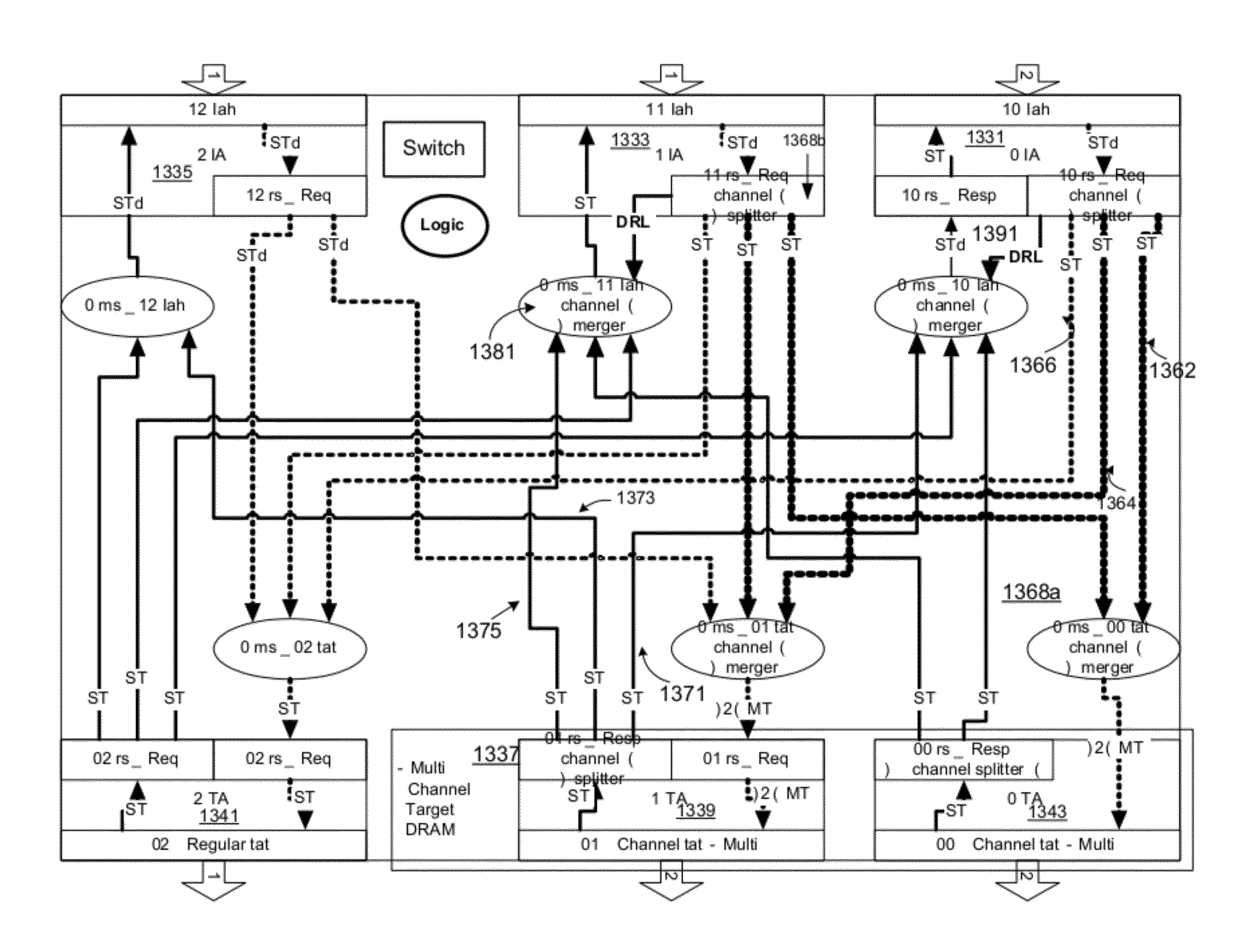
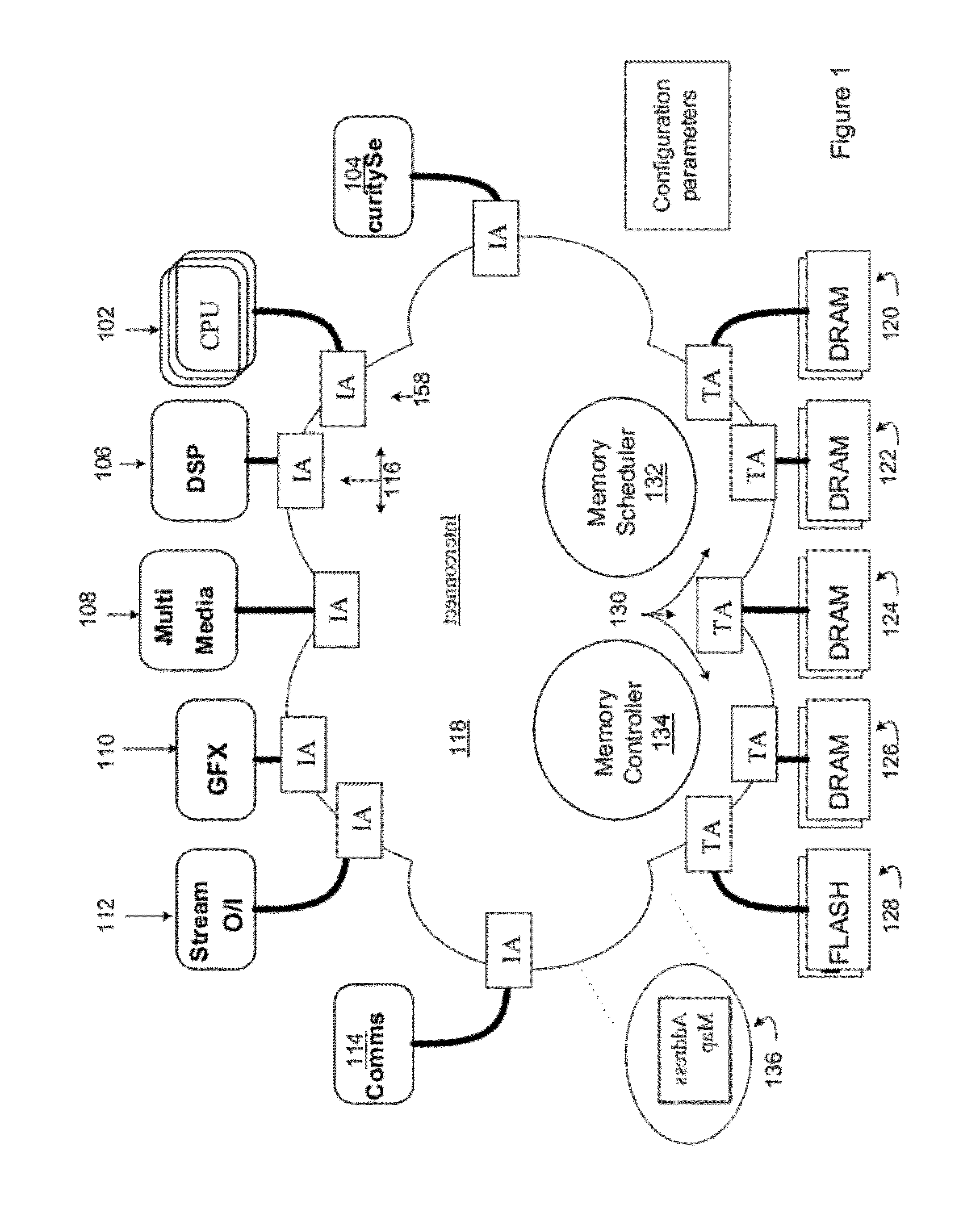
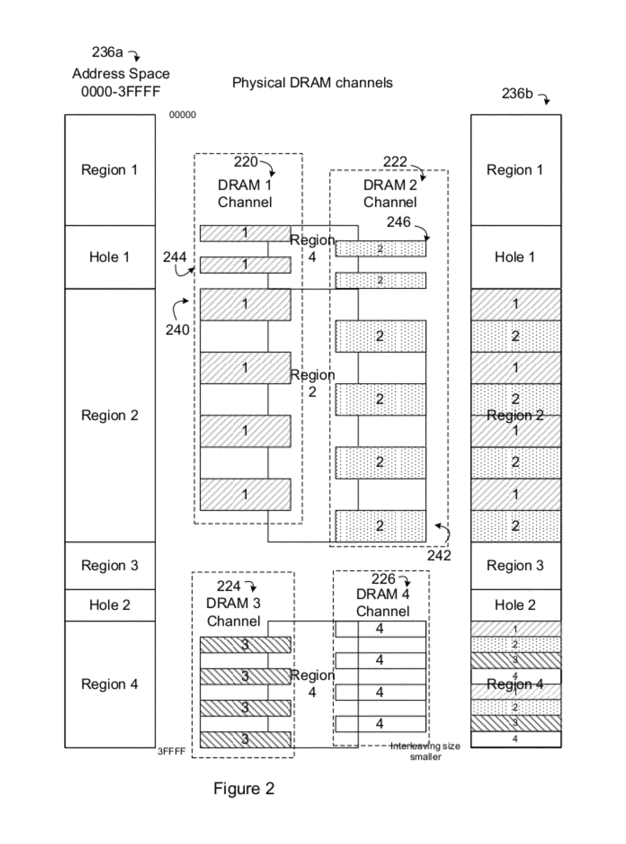
[0007]A method, apparatus, and system are described, which generally relate to an integrated circuit having an interconnect that has multiple initiator IP cores and multiple target IP cores that communicate request transactions over an interconnect. The interconnect provides a shared communications bus between the multiple initiator IP cores and multiple target IP cores. The flow control logic for the interconnect applies a flow control splitting protocol to permit transactions from each initiator thread and / or each initiator tag stream to be outstanding to multiple channels in a single aggregate target at once, and therefore to multiple individual targets within an aggregate target at once. The combined flow control logic and flow control protocol allows the interconnect to manage simultaneous requests to multiple channels in an aggregate target from the same thread or tag at the same time.

Problems solved by technology

This forced the software and system functional block to have to be aware of the organization and structure of the memory system when generating initiator requests.
In the traditional approach, the traffic may be split deeply in the memory subsystem in central routing units, which increases traffic and routing congestion, increases design and verification complexity, eliminates topology freedom, and increases latencies.
The created centralized point can act as a bandwidth choke point, a routing congestion point, and a cause of longer propagation path lengths that would lower achievable frequency and increase switching power consumption.

Method used


Image

  • Interconnect that eliminates routing congestion and manages simultaneous transactions
  • Interconnect that eliminates routing congestion and manages simultaneous transactions
  • Interconnect that eliminates routing congestion and manages simultaneous transactions

Examples


Embodiment Construction

[0026]In the following description, numerous specific details are set forth, such as examples of specific data signals, named components, connections, number of memory channels in an aggregate target, etc., in order to provide a thorough understanding of the present invention. It will be apparent, however, to one of ordinary skill in the art that the present invention may be practiced without these specific details. In other instances, well known components or methods have not been described in detail but rather in a block diagram in order to avoid unnecessarily obscuring the present invention. Further specific numeric references, such as first target, may be made. However, the specific numeric reference should not be interpreted as a literal sequential order but rather interpreted that the first target is different than a second target. Thus, the specific details set forth are merely exemplary. The specific details may be varied from and still be contemplated to be within the spiri...


PUM


Abstract

A method, apparatus, and system are described, which generally relate to an integrated circuit having an interconnect. The flow control logic for the interconnect applies a flow control splitting protocol to permit transactions from each initiator thread and / or each initiator tag stream to be outstanding to multiple channels in a single aggregate target at once, and therefore to multiple individual targets within an aggregate target at once. The combined flow control logic and flow control protocol allows the interconnect to manage simultaneous requests to multiple channels in an aggregate target from the same thread or tag at the same time.

Description

RELATED APPLICATIONS[0001]This application is continuation of patent application Ser. No. 12 / 144,987, filed Jun. 24, 2008, titled “Various methods and apparatus to support outstanding requests to multiple targets while maintaining transaction ordering,” which is related to and claims the benefit of U.S. Provisional Patent Application Ser. No. 60 / 946,096, titled “An interconnect implementing internal controls,” filed Jun. 25, 2007.NOTICE OF COPYRIGHT[0002]A portion of the disclosure of this patent document contains material that is subject to copyright protection. The copyright owner has no objection to the facsimile reproduction by anyone of the software engine and its modules, as it appears in the Patent and Trademark Office Patent file or records, but otherwise reserves all copyright rights whatsoever.FIELD OF THE INVENTION[0003]Embodiments of the invention generally relate to an interconnect implementing internal controls to eliminate routing congestion.BACKGROUND OF THE INVENTIO...

Claims


Application Information

Patent Timeline
Patent Type & Authority Applications(United States)
IPC IPC(8): G06F13/42
CPCG06F12/0607Y02D10/13G11C7/1072G06F15/17375Y02D10/00
Inventor WINGARD, DREW E.CHOU, CHIEN-CHUNHAMILTON, STEPHEN W.SWARBRICK, IAN ANDREWVAKILOTOJAR, VIDA
Owner META PLATFORMS TECH LLC
Why Eureka
Try Eureka