Transcritical thermally activated cooling, heating and refrigerating system

a thermal activated cooling, heating and refrigerating system technology, applied in the direction of machines/engines, lighting and heating apparatus, machine operation modes, etc., can solve the problem of super-critical high-pressure portion of the vapor expansion circui

Inactive Publication Date: 2012-02-16
CARRIER CORP
View PDF17 Cites 26 Cited by
  • Summary
  • Abstract
  • Description
  • Claims
  • Application Information

AI Technical Summary

Problems solved by technology

The pump and expander are so sized and designed that the high press

Method used


Image

  • Transcritical thermally activated cooling, heating and refrigerating system
  • Transcritical thermally activated cooling, heating and refrigerating system
  • Transcritical thermally activated cooling, heating and refrigerating system

Examples


Embodiment Construction

[0028]While the present disclosure has been particularly shown and described with reference to the preferred mode as illustrated in the drawing, it will be understood by one skilled in the art that various changes in detail may be effected therein without departing from the spirit and scope of the disclosure as defined by the claims.

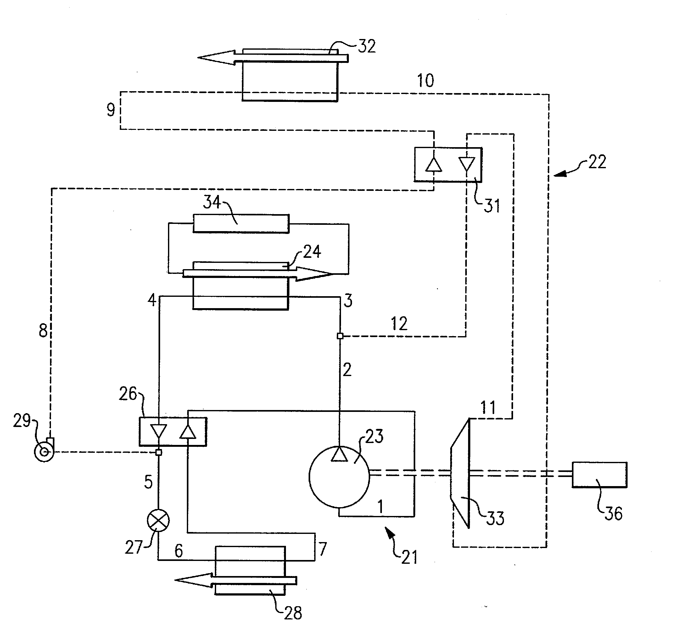
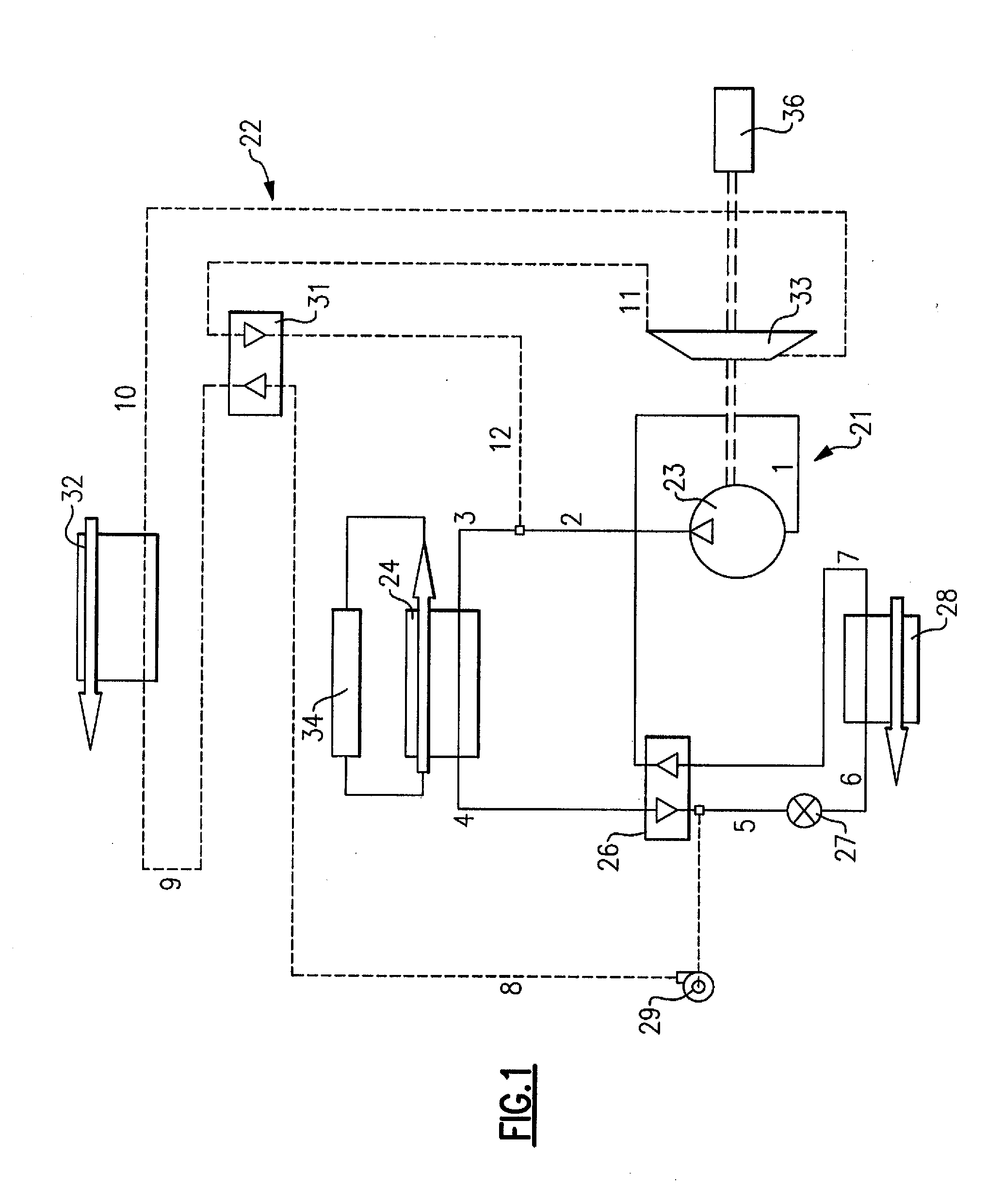
[0029]In accordance with FIG. 1 a thermally activated refrigerant system incorporates a vapor compression circuit 21 shown as solid lines and a vapor expansion circuit 22 shown as dashed lines. The vapor compression circuit 21 includes a compressor 23, a condenser 24, a liquid-to-suction heat exchanger 26, an expansion device 27, and an evaporator 28. The vapor expansion circuit 22 consists of a pump 29, a topping heat exchanger 31, a heater 32, an expander 33, and the condenser 24. A refrigerant vapor stream at the outlet from the compressor and a vapor refrigerant stream at the outlet from the expander are connected at the condenser inlet to provide a ...


PUM


Abstract

A combined vapor compression and vapor expansion system uses a common refrigerant which enables a super-critical high pressure portion and a sub-critical low pressure portion of the vapor expansion circuit. Provision is made to combine the refrigerant flow from the vapor expander and from the compressor discharge. The outdoor heat exchanger is so sized and designed that the working fluid discharged therefrom is always in a liquid form so as to provide a liquid into the pump inlet. The pump and expander are so sized and designed that the high pressure portion of the vapor expansion circuit is always super-critical. A topping heat exchanger, liquid to suction heat exchanger, and various other design features are provided to further increase the thermodynamic efficiency of the system.

Description

CROSS REFERENCE TO RELATED APPLICATION[0001]This disclosure relates to pending U.S. application Ser. No. 07 / 18958, assigned to the assignee of the present disclosure.[0002]Reference is made to and this application claims priority from and the benefit of U.S. Provisional Application Ser. No. 61 / 173,776, filed Apr. 29, 2009, entitled “TRANSCRITICAL THERMALLY ACTIVATED COOLING, HEATING AND REFRIGERATING SYSTEM”, which application is incorporated herein in their entirety by reference.TECHNICAL FIELD[0003]This disclosure relates generally to vapor compression systems and, more particularly, to a combined vapor compression and vapor expansion system.BACKGROUND OF THE DISCLOSURE[0004]It is known to combine a vapor compression system with a vapor expansion, i.e. Rankine cycle, system. See, for example, U.S Pat. No. 6,962,056, assigned to the assignee of the present invention, and U.S Pat. No. 5,761,921.[0005]U.S. Pat. No. 5,761,921 generates power in the Rankine cycle which is then applied ...

Claims


Application Information

Patent Timeline
IPC IPC(8): F01K25/08F25B1/00
CPCF01K17/02F01K17/04F25B9/008F25B13/00F25B27/02F25B2309/061Y02A30/274
Inventor VAISMAN, IGOR B.WAGNER, TIMOTHY C.SANGIOVANNI, JOSEPH J.WALKER, CRAIG R.
Owner CARRIER CORP
Why Eureka
Try Eureka