
Method of Manufacturing an Optical Fibre Preform

a manufacturing method and optical fibre technology, applied in glass making apparatus, manufacturing tools, instruments, etc., can solve the problems of increased attenuation losses and serious attenuation of the signal being carried, and achieve the effect of small attenuation losses and strong absorption peak

Active Publication Date: 2012-02-16
DRAKA FIBRE TECH BV +1
View PDF0 Cites 0 Cited by
  • Summary
  • Abstract
  • Description
  • Claims
  • Application Information

AI Technical Summary

Benefits of technology

The present invention provides a method for making a preform that does not have any hydroxyl groups. Additionally, the invention provides a method for making optical fibers that have low attenuation losses caused by hydroxyl groups. These fibers also have strong absorption peaks at 1240 nm and 1385 nm.

Problems solved by technology

The use of such a fibre for telecommunication purposes requires the fibre to be substantially free from contamination, since such contamination can cause serious attenuation of the signal being carried if great fibre lengths are used.
Although prior art methods exist for preventing the incorporation of such —OH-groups into the optical glass fibre, for example by carrying out a chlorination step following the deposition step in the case of porous glass structures, as known from U.S. Pat. No. 4,675,038, or by adding fluorine during the chemical vapour deposition reaction, for example, as known from European patent application No. 0 127 227, both prior art methods have this drawback that an additional amount of chlorine or fluorine, respectively, will find its way in the final glass structure, leading to increased attenuation losses caused by Rayleigh scattering.

Method used


Image

  • Method of Manufacturing an Optical Fibre Preform

Examples


Embodiment Construction

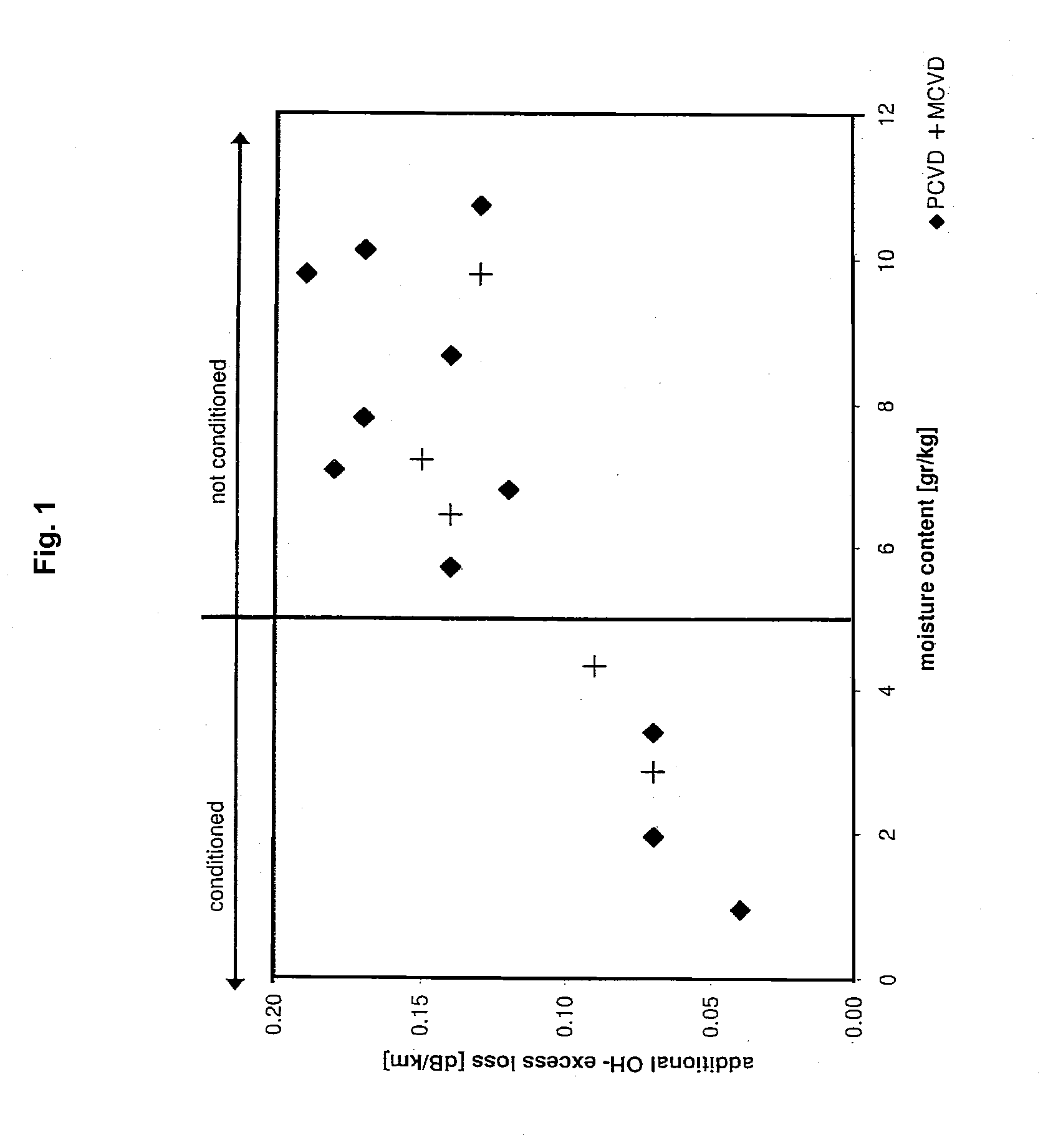
[0012]The invention as referred to in the introduction is characterized in that the deposition step is carried out in an environment in which the substrate is present in a conditioned atmosphere, which conditioned atmosphere has a moisture content lower than that of the non-conditioned atmosphere.

[0013]It has appeared to be possible to achieve a significant reduction of the attenuation losses caused by hydroxyl groups by conditioning the environment in which the preforms for the glass fibre production are manufactured. The term “conditioned atmosphere” is to be understood to mean an atmosphere having a significantly lower moisture content than the atmosphere that has generally been used so far.

[0014]For an internal deposition process in which glass-forming compounds are added to the interior of a substrate tube, which substrate tube is contracted into a solid preform, it is desirable that the contraction step be carried out in an environment in which the atmosphere is conditioned, w...


PUM

PropertyMeasurementUnit
humidityaaaaaaaaaa
humidityaaaaaaaaaa
temperatureaaaaaaaaaa

Abstract

The present invention relates to a method for manufacturing a preform for optical fibres, wherein deposition of glass-forming compounds on the substrate takes place. The present invention furthermore relates to a method for manufacturing optical fibres, wherein one end of a solid preform is heated, after which an optical fibre is drawn from said heated end.

Description

CROSS REFERENCE TO PRIORITY APPLICATIONS[0001]This application is a continuation of commonly assigned U.S. patent application Ser. No. 10 / 959,331 for A Method for Manufacturing a Preform for Optical Fibres as Well as a Method for Manufacturing Optical Fibres, (filed Oct. 7, 2004, and published Jun. 9, 2005, as U.S. Patent Application Publication No. 2005 / 0120751 A1), now U.S. Pat. No. 8,006,518, which itself claims the benefit of Dutch Application No. 1024480 (filed Oct. 8, 2003 at the Dutch Patent Office). Each of the foregoing patent applications, patent application publication, and patent is hereby incorporated by reference in its entirety.FIELD OF THE INVENTION[0002]The present invention relates to a method for manufacturing a preform for optical fibres, wherein deposition of glass-forming compounds on a substrate takes place. The present invention furthermore relates to a method for manufacturing optical fibres, wherein one end of a solid preform is heated, after which an optic...

Claims


Application Information

Patent Timeline
Patent Type & Authority Applications(United States)
IPC IPC(8): C03B37/018C03B37/027C03B37/014
CPCC03B37/01413C03B37/01807C03B37/0183C03B2201/04C03B2201/075G02B6/00C03B37/018
Inventor SIMONS, DENNIS ROBERTTERPSMA, JELLE PHILIPGOOIJER, FRANS
Owner DRAKA FIBRE TECH BV
Learn More